Relays are pretty safe to use without any special isolation like optocouplers. The reason people recommend optocouplers in DIY projects... well because its DIY and an optocoupler is safer in case of something going wrong.
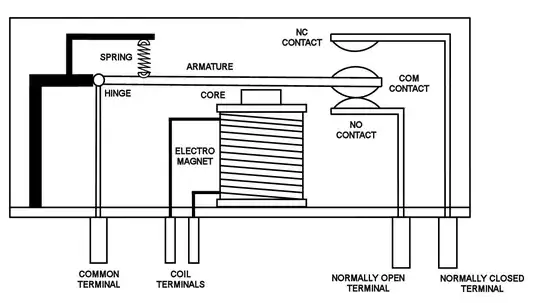
The input pins power a coil and push or pull a lever using some kind of snap hinge to eliminate bounce and sparks. So you are already isolated by air (~1000v per 1mm of air protection). Optocouplers turn on the coil using a light beam on the switch, which help isolate the MCU from flyback EMF, and possible relay short circuit.
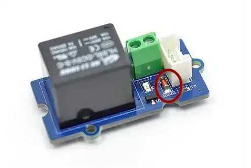
A relay will (or should) have a diode to protect your device from electromagnetic flyback voltages, and the one from Seeed has this built in.
The widely accepted way of driving a relay with a MCU pin is to use a transistor to "switch" GND and power the relay from a separate dedicated power supply/pin instead form the IO.
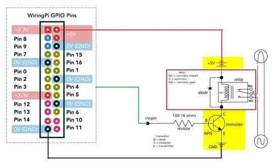
You would then supply 5Volts into the relay Vcc direct from the 5V apapter that connects to the Raspberry, NOT from the Raspberry itself. The transistor, when you pull up a GPIO will "connect" the GND and the relay will work. Transistor have diodes built in and also also offer other protection to the GPIO. Transistors are well marked and you you can use a variety of them. If anything weird happens with the relay the transistor will blow up saving the MCU in normal environments. The worst case scenario is lightning striking it, then, sadly allot of things break.
The schematics for the device you pointed out already contain all this circuitry. Isnt that nice of them :) It means you are protected and you just need to connect 3 wires, since all the above is ALREADY on the PCB :) Notice a 4.7K resistor in between D1 and Q1. Q1 is the transistor and you also have an LED show when the relay is active :)
Now just take care when connected 220v to J1 - You run LIVE to the relay. So you switch LIVE on AC and not GND. Do not connect LIVE and NEUTRAL into there.
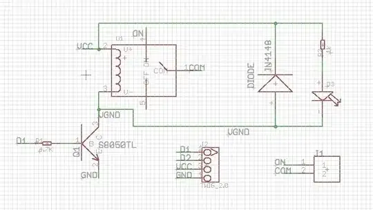
- D1 - Connect to Raspberry Pi GPIO PIN
- D2 - Unused
- VCC - COnnect to 5V on Pi
- GND - Connect to GND on Pi