0

I'd like to set up a switch (on the outside of the case/enclosure) to power up/power down (halt state) a RP zero.

I have a 2-pin SPST on-off latching switch (specifically, this one: https://thepihut.com/products/spst-on-off-latching-miniature-toggle-switch), but all the examples I've seen of "power buttons" use momentary switches. Also, some of those examples use resistors and some don't (which I gather is to do with which pins you connect to, although I'm not really clear on that).

Can anyone help me understand how to wire up the latching switch and whether I need to use resistors, or perhaps point me in the direction of some easy-to-understand documentation?
Lenny
  • 13
  • 3

1 Answers1

0

You can see your switch as a 3-pin SPDT switch with one pin missing. Your common pin (the one in the center of your component) is permanently connected. Your common pin will stay unconnected if the switch is on the left. If you switch to the right, your common and right pins will be shorted.

For your application, I see two possibilities :

  • You could connect your common pin your 5V power supply and the right pin to the 5V of your Rpi Zero. Your Raspberry will be either powered up or unpowered and you don't need any resistor. Your Pi will be turned off even if the firmware inside crashes.

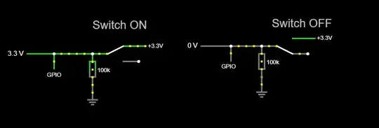
  • You could connect your common pin to a 3V3 and the right pin to a GPIO, using a pull-down circuit for your GPIO if needed (if you are not using internal pull-up/pull-down in your device). Like this, you can programmatically halt your Rpi when the GPIO goes high. Note that in this case your Pi will be turned off only if your program is still running.

Here is a quick illustration of the circuitry

Pulldown circuit for RPi gpio

Bibibou
  • 80
  • 9