I'm trying to connect the signal from a doorbell to a Raspberry Pi Zero 2W to modernize the existing system with IoT capabilities. I did some measurements and I found that the terminal that powers the indoor unit changes from 0 V to 13.3 V DC when the doorbell button of the outdoor unit is pressed.
Since I plan to use the same power supply of the doorbell to power the Pi (using a 5V buck converter with a 2.5 A output current rating, but that's another matter), GND would be common to both devices. Searching for best practices to adapt the signal to the Pi's 3.3V logic, I came across this great answer:

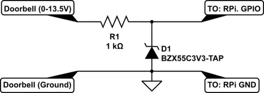
So, I have two questions regarding the circuit above:
1) In case of an overvoltage transient, I understand the diode D1 starts to conduct and sources the current to the 3.3V rail while clamping the voltage. Do I have to disable the internal pull-up resistor from the GPIO pin for this protection to work properly?
2) With the given values for R1 and R2, the voltage divider would heat quite a bit when the doorbell is ON (roughly 190 mW power being dissipated by R1), is it OK to change the values to 6.8k and 1.2k ohms, or that would be detrimental to the overvoltage protection discussed above (higher series resistance)?
Finally, I'd like to add that the wiring between the doorbell's outdoor and indoor units is around 20m long, but it's done over a UTP cable.
Thanks a lot in advance.
EDIT: Here's a diagram of what I'm trying to do. The green box is the one that's related to the questions of this post.
