I've just started working through the Freenove ultimate starter kit for the Pi Pico, and I'm having trouble understanding why it has so many resistors in this circuit.
I'm following the tutorial document at https://github.com/Freenove/Freenove_Ultimate_Starter_Kit_for_Raspberry_Pi_Pico/blob/master/Python/Python_Tutorial.pdf and have made it to project 2.1.
The relevant circuit diagram is attached.
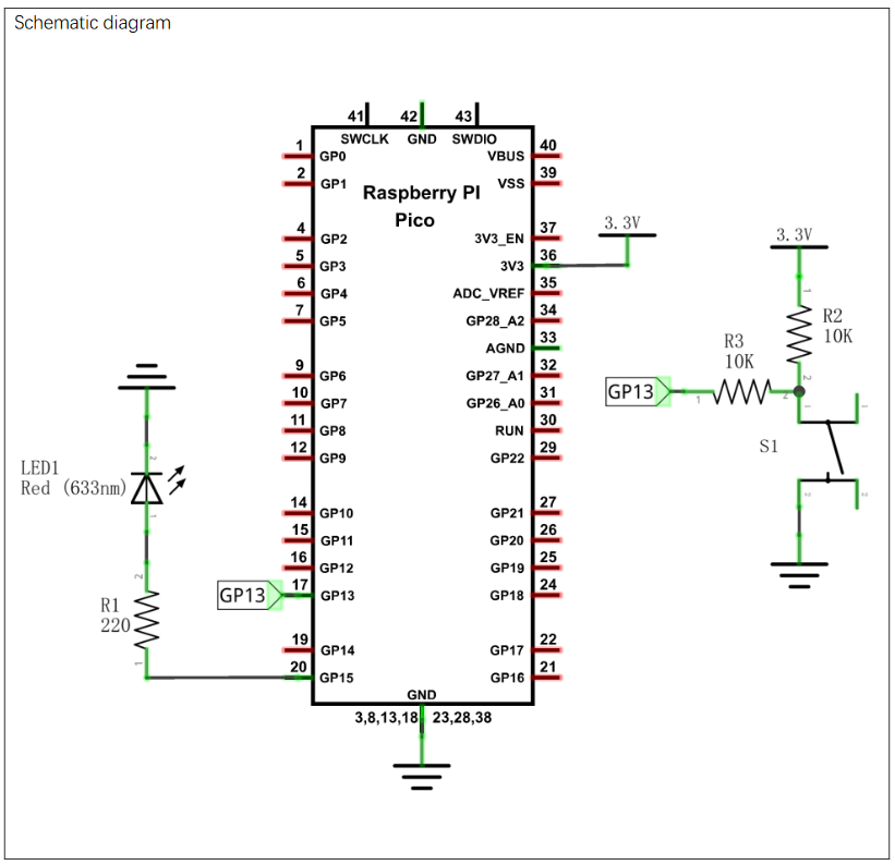
I understand it uses a 220ohm resistor to prevent the LED burning out.
It also uses 2 10k resistors connected to the button - these are the ones that I don't understand. I'm trying to clarify a number of things:
- Am I correct in thinking that 2 10k resistors in series are the equivalent of a single 20k resistor?
- Is this done so that we're not passing too much current to the GP13 pin?
I'm having trouble finding an answer as to what the acceptable inputs for the GPIO pins are - the closest I've found is What are the min/max voltage/current values the gpio pins can handle? which recommends no more than 0.5mA. But that's an old post, and not specifically about the Pico.
- Assuming the GPIO pin could take the full 3.3V @ whatever Amps, would I need either of these resistors?
- Could I remove safely remove just R2?
This is my first introduction to electronics, so I'm very much in the camp of not even knowing what topics I need to understand. Any advice would be greatly appreciated.