I appreciate any help in this puzzling situation - I'm at a loss here.
As part of a Robotics project, I'm trying to control a motor with a Raspberry Pi. The exact components I'm using are:
- A Raspberry Pi 3b+
- A goBILDA Yellow Jacket 12V DC Gear Motor, 30RPM, Gear Ratio 188:1
- A goBILDA 1x15A Speed Controller
- A 12V NiMH Battery Pack
- A bidirectional level shifter, like this one
This Speed Controller works with signals similar to a servo, with PWM signals in the range 1050-1950 microseconds.
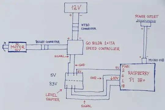
I followed the instructions on this manufacturer's video, and adapted the instructions that come for ARDUINO to a Raspberry. This resulted in the following wiring:
I also tried to code a very simple code that would do the same as the manufacturers example code, to generate the proper PWM signals to
start at rest, accelerate the motor in one direction until 50% max speed, decelerate, halt, accelerate in the other direction until 50% max speed, decelerate, finally halt again.
I calculated the duty cycles to do this in arbitrary steps. I hope the calculation are right: For a 50Hz PWM signal, I believe that a duty cycle of 7.5% means rest (1500us), while 5.25% means full reverse (1050us) while 9.75% means full forward speed (1950us).
import RPi.GPIO as GPIO
from time import sleep
print('Starting Program')
Set the GPIO to be used with BOARD numbers:
GPIO.setmode(GPIO.BOARD)
Setup the PIN 18 as a GPIO output:
GPIO.setup(18,GPIO.OUT)
Creates the PWM object in PIN 18 with frequency 50Hz:
PWM_object = GPIO.PWM(18,50)
try:
# Moving Forward, increase duty cycle..
# Accelerating..
# Temba, at rest:
PWM_object.start(7.5)
sleep(2)
# Step 1
PWM_object.ChangeDutyCycle(7.725)
sleep(5)
# Step 2
PWM_object.ChangeDutyCycle(7.95)
sleep(5)
# Step 3
PWM_object.ChangeDutyCycle(8.175)
sleep(5)
# Step 4
PWM_object.ChangeDutyCycle(8.4)
sleep(5)
# Step 5: 50% forward speed
PWM_object.ChangeDutyCycle(8.625)
sleep(5)
# Decelerating..
# Step 6
PWM_object.ChangeDutyCycle(8.4)
sleep(5)
# Step 7
PWM_object.ChangeDutyCycle(8.175)
sleep(5)
# Step 8
PWM_object.ChangeDutyCycle(7.95)
sleep(5)
# Step 9
PWM_object.ChangeDutyCycle(7.725)
sleep(5)
# Step 10: Rest
PWM_object.ChangeDutyCycle(7.5)
sleep(5)

# Moving Backward, decreasing duty cycle..
# Accelerating..
# Step 11: Reversing
PWM_object.ChangeDutyCycle(7.275)
sleep(5)
# Step 12:
PWM_object.ChangeDutyCycle(7.05)
sleep(5)
# Step 13:
PWM_object.ChangeDutyCycle(6.825)
sleep(5)
# Step 14:
PWM_object.ChangeDutyCycle(6.6)
sleep(5)
# Step 15: 50% reverse speed
PWM_object.ChangeDutyCycle(6.375)
sleep(5)
# Decelerating..
# Step 16:
PWM_object.ChangeDutyCycle(6.6)
sleep(5)
# Step 17:
PWM_object.ChangeDutyCycle(6.825)
sleep(5)
# Step 18:
PWM_object.ChangeDutyCycle(7.05)
sleep(5)
# Step 19:
PWM_object.ChangeDutyCycle(7.275)
sleep(5)
# Step 20: Rest
PWM_object.ChangeDutyCycle(7.5)
sleep(5)

PWM_object.stop()
GPIO.cleanup()


except KeyboardInterrupt:
    PWM_object.stop()
    GPIO.cleanup()
print('Program Complete.')
However, the motor moved clockwise (the first part of the code) but not counterclockwise (the second part).
I've tried, to no luck:
- Hooking up the battery directly to the motor, with both polarities --> It spins both ways fine.
- Send the motor straight to full reverse --> Did not move.
- Change the signal PIN to the speed controller with code above --> Did not move too.
- Repeat the test with an ARDUINO, and the manufacturer's code --> It moved successfully in both directions, hinting that the problem is with the RPi or my code.
How can I make this motor move both ways?
