I am measuring a hall sensor included in a motor.
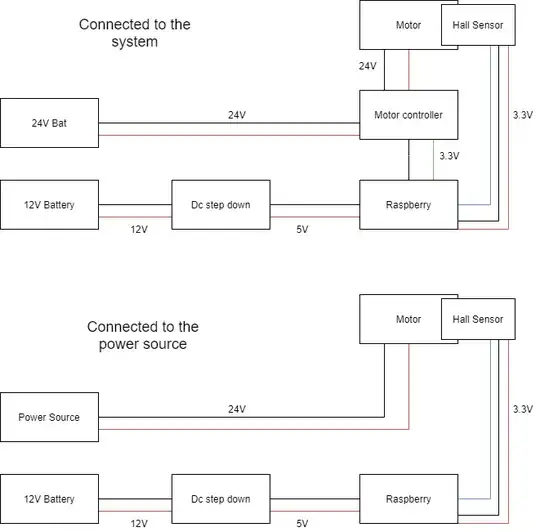
A Raspberry Pi 3b+ controls a Sabertooth 2x32 motor controller through radio Signal (ppm) and the Sabertooth output is connected to the motor. I get wrong measurements, I am using pin risings to count the hall readings and but the read is much faster (x50) than the real turns. Weird is that if I connect the motor to a power source, the readings will be perfect.
Any ideas of what could be causing this? I have a 24V and a 12V batteries. The raspberry is powered after a DC step-down from the 12V one. The motor controller is connected directly to the 24V battery. I had tried with pigpio and RPi.GPIO libraries and they behaved the same.
[Update]: I tested moving the wheel with the hand and the lectures were correct. Even with the Sabertooth connected but now powering the motors.
[Update 2]: Code deleted as it had nothing to do. PWM signal generated from the motor makes interference. That's why with the power source or manual movement everything worked. Also, the interference is being captured in the hall sensor. When optical encoders were used no interference was measured.
[Conlcusion]: Powering motors with PWM and measuring with hall sensors is a bad combination (at least in this set-up which doesn't address the interference) Thanks, everyone!
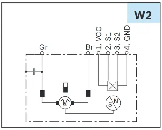
Motor: Bosch motor CDP 0 986 337 250 24V 6A rated geared 54:1
Controller Sabertooth 2x32
System diagram:

