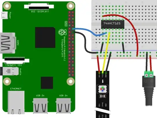
Before I start, I should note that I have never used a Raspberry Pi before, so my only experience is trying to get this project to work.
I recently bought ALITOVE WS2811 12mm (5 V) LED lights in the hopes that I could hang them in my room and control the colors. I want to control the colors through a Raspberry Pi by using the Neopixels python library. I was able to create an ssh connection to the Raspberry Pi with my computer and run python files on the pi. However, I have been struggling to control the colors of the LEDS using a GPIO pin. Specifically, I have been using the GPIO18 pin. I am following this tutorial and am using this circuit:
When I plug everything in with a 5V 10A power supply, nothing turns on, even when I run the code. However, if I unground the Pi, then the LED lights start flashing randomly.
The current steps that I have taken to try and fix the error are: I checked my circuit and made sure the level shifter was properly oriented and the pins of the level shifter were correct according to the tutorial. I also tried directly connecting the DI line to the LEDs and was able to control the lights properly (obviously the LEDs were very dim, but it was a proof of concept).
I was hoping someone could help me as I am completely lost at this point. I have exhausted every idea to fix the error and can't seem to find answers online that don't already match the circuit above.
I also have a side question about powering my pi. Can I power the pi using the power supply too, or do I need to power it through a micro USB cable? Thank you.
When I directly connected the DI line to the Pi, I did not use an external power source. I just wired the pi's power, GPIO18 pin, and ground directly to the LEDs. This allowed me to control the lights, but the pi does not provide anywhere close to the necessary output, so the one light I had it turn on was dim. I just tried directly connecting the DI line to GPIO18 without level-shifting, but I am still connecting the LEDs to an external power source and am having the same issue as before. This time, when I unground the pi, the lights are all white, even though I am telling them to be red and green ((0, 255, 0) and (255, 0, 0)). Here is the code I am running:
import board
import neopixel
pixels = neopixel.NeoPixel(board.D18, 50, auto_write=True)
pixels.fill((0, 255, 0))
pixels[0] = (255, 0, 0)
pixels[1] = (255, 0, 0)
I also tried out the other two sets of the same LEDs I got, and when I ran the code with the circuit above, except I added a 3K ohm resistor in series with the pi ground, the first LED randomly changed colors, and a couple of LEDs, not necessarily adjacent, went to a couple of random colors. Every time I ran the code, a new set of LEDS would light up with a couple of random colors.
I tried connecting the unused /OE and inputs of the level-shifter, and it did not seem to work. However, it definitely did something. I checked the voltage of the data line output, and without the added connections, the voltage was 3.3 V. With the connections, I got 0.15 V. The black lead was on the GND of the level-shifter and the red lead was on pin three of the level-shifter. I investigated what would happen if I unplugged the GND of the pi and the voltage went to 1.5 V. I also tested the power supply and got 5 V as expected, so my multimeter seems to be working. I might just choose a different way to transform the voltage. I should also note that I did check that the input was going in from the correct direction.
Here is a picture of my circuit:
https://ibb.co/nnkQPZG https://ibb.co/LdNtmyy
Here is an image of directly connecting the pi and LEDs: https://ibb.co/SwpzNHz
