12

For my school engineering project, I have a coin acceptor device which I would like to link to the Raspberry Pi. However the device requires 12V in power. I have an idea of what to do to power the device, however I have heard that there is a risk of blowing the Pi when I hook the device up to the GPIO ports/breadboard.

Is there anything I can do to get around this? Or is this not likely to happen?

Here's the link to the coin acceptor I'm hoping to use: http://www.amazon.co.uk/Sintron-Acceptor-Vending-Machine-Message/dp/B00C16P03I/ref=sr_1_1?ie=UTF8&qid=1385370033&sr=8-1&keywords=coin+acceptor

Steve Robillard
  • 34,988
  • 18
  • 106
  • 110
ChaoticPanda
  • 395
  • 2
  • 3
  • 7

4 Answers4

6

As I read your question, you need to power the Coin Acceptor using 12v, and reading the output using your RPi.

To power the Coin Acceptor it is best you use an external power supply, as the coil in the acceptor might reset the RPi as it draws a relative large ammount of current when it operates.

Find a 12v power supply, connect - on the PSU to a common ground and + on the PSU to the coin acceptor. That should allow you to configure the coins that should be validated.

I have a similar coin validator, and mine works by connecting the COIN pin to ground or leaving it unconnected (not entirely, it just has a large resistance). Depending on your setting on the switch, COIN is either NC/Normally Closed (default GND) or NO/Normally Open (default not connected). When the acceptor delivers a pulse, the mode switches and you can detect the change using the RPi.

In order to be able to detect the change, you need to drive the COIN pin to a higher voltage, else it will be a voltage comparable to GND at all times.

Wire the COIN pin to the input on the RPi, through a resistor (try 1k ohm). To pull up (when COIN is on the acceptor is open), wire the 3.3v on the RPi to the input on the RPi (I suggest you use the same resistance).

That will lead to a voltage of ~3.3 v when the contact is open, and a voltage of about half when the contact is closed. If the RPi becomes unstable, you might be drawing too much current, so try to move it up. If the RPi can't detect anything on the pin, try to go with a smaller resistor.

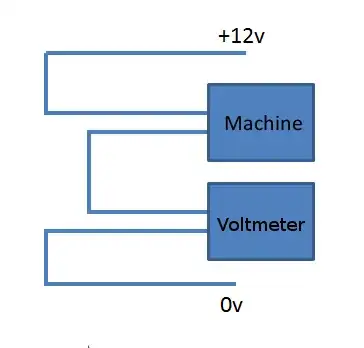
Make sure to measure everything before you connect it to the RPi, as your coin acceptor might work in a different way. If you can find another 3.3v or 5v source, try to connect instead of 3.3v on the RPi, and measure over GND and the RPi input using a multimeter or oscilloscope.

You can get a really good help with any of this on the electronics stackoverflow - they can help you with wiring and components, so you make sure you don't blow anything up. :-)

Jervelund
  • 476
  • 2
  • 5
2

Something like this? This means the Pi is telling something else to do the switching,and not itself - the Pi can only output 3.3V, up to circa 50mA through the GPIOs.

Schematic

For the transistor, something like a T!IP31C should do well for this voltage. It can take up to 100 Volts, and around 3 Amps - but this depends how much current does the machine draws. If it anything above 1 or 2 Amps, you need a relay in the circuit in place of the NPN transistor.

Here is a diagram of how to measure the current (Make sure that the multimeter is set to Amps, not milliAmps, or you will blow its fuse):

Current Test

For more info on connecting a relay (may add diagram later) - see here

Wilf
  • 2,533
  • 3
  • 23
  • 39
0

From what I found online, there are at least two version out there,

On one it seems the coin-line only outputs 3.3v. But you'd have to measure it on your model using a multimeter. If it's higher, you could use a voltage divider to bring down the voltage to 3.3V (a lot cheaper that one of those opto-isolaters)

The other version has the coin-line pull to ground, so here you'd only need an (internal) pull-up resistor.

Gerben
  • 2,420
  • 16
  • 17
0

According to the adafruit product page, you need to use a pullup resistor on the coin wire (white). Then listen for pulses on the pi's GPIO pin and count them to tell you which coin was inserted. Of course you'll need to connect the ground of the 12v supply to the ground of the pi's supply too. And I guess you've already read the instructions how to program the device to recognise the coins you want to use.

francis
  • 765
  • 8
  • 21