Just like a lot of people I'm using a RPi as a NTP server. There is a nice thread about it here: Switch out the X1 Oscillator on a RPI 2/3
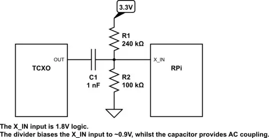
User @colintd had a brilliant answer about switching the stock oscillator with a TCXO and he also mentions: "As a 3V3 part it needed AC coupling via a 1nF capacitor, and the DC level setting with 240K & 100K resitors"
I was wondering if he (or anyone) can explain how this capacitor and resistors are connected? Perhaps a small circuit diagram?
Many thanks!
PS. As a newbie here I wasn't able to reply to the original thread, hence a new one.