I am a beginner when it comes to electronics so I would appreciate your help with a simple project I am working on and have been struggling with for several days.
The idea is that I have a PIR Sensor outputting to GPIO 24 on my Pi. Via a python script, I would like to switch on a 12-volt LED strip with its own external power supply. I am able to see when motion is detected via the script, so that is working fine. The issue however is that I am not able to properly use my mosfets to act as a switch. In order to take it step by step, for now I am trying to output signal to my mosfet Gate via GPIO 24, and manually alter the PWM via terminal (instead of using the PIR output).
My scheme is similar to this: https://screen.sh/cAaSbZiM - however not using the battery, and using the GPIO 24 output instead of PIR.
I have tried this with a IRLB8721 mosfet, but realized it needs a higher voltage than what the GPIO can provide. The most suitable one I could find then was the IRF3205, seeing that it is used more frequently with Raspberry PI/Arduino applications, but unfortunately this is also not working. It seems like my GPIO voltage is still too low.
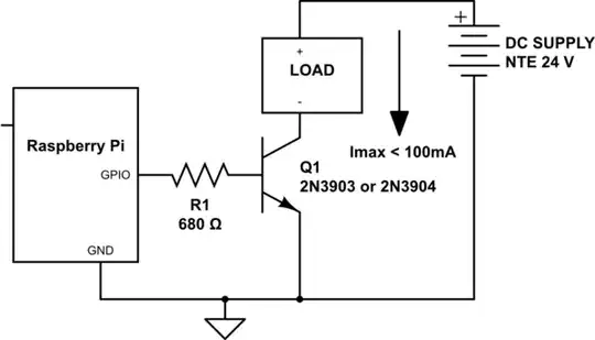
Alternatively I have a couple of 2N3904 transistors available but I am not entirely sure how I can use these without frying them.
I have noticed that when using the IRLB8721, my LEDs are always on, and I am not able to switch them off. I did make sure not to mix up the Drain and Source, yet still not working.
Could you please guide me in the right direction? I am not able to get any other components for another week, so I am stuck with a diode, couple of 1kOhm resistors, and these 3 types of transistors/mosfets/ Is there anything I can do to fix this?
I have looked this up extensively and tried it on my breadboards but with no success. Only lead I have is pointing to a fairchild mosfet which I am not able to get to for weeks.
Thank you.
