3

I'm building a doohickey that uses 4 pairs of momentary switches. For prototyping, I'm using standard little pushbutton switches that plug into a breadboard, two for each pair. When I've finished the code and am done playing with it, I want to use 4 SPDT momentary toggle switches instead of the four pairs of pushbuttons.

Now, with my limited knowledge of electrical/electronic stuff, it seems to me that the SPDT toggle switch is no different from two SPST pushbuttons. I've learned, however, that the real world doesn't always do what you think it should (I'm a software guy where programs do exactly what you tell them to do) so I thought I should ask before I do something I'll regret.

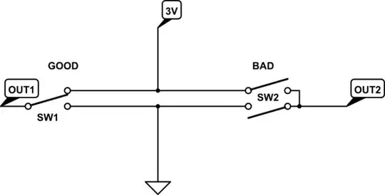
I'm not planning on using any resistors or anything; each button just goes from GND to a GPIO pin and the code sets them up thusly:

GPIO.setmode(GPIO.BCM)
GPIO.setup(switch01, GPIO.IN, pull_up_down=GPIO.PUD_UP)

It works as-is with the pushbuttons; will I be getting myself in trouble if I switch to the SPDT toggles?

3 Answers3

4

Only reasons I would NOT use them are:

  • You end up with a connector not connected to anything and this can be misleading long term as you may wonder why
  • Some can be physically larger
  • Some can cost more though not normally an issue for the hobby
  • Labels on the switch can have both positions marked
2

To answer your question, yes it is probably perfectly fine to use an SPDT in place of a SPST. Depending on the design, if it is soldered in place it may even add some additional mechanical stability to the switch.

But to also clarify it is NOT like 2 separate SPST switches. It just allows for making a connection in the normal (unpressed) state, in addition the pressed state that an SPST provides. This could be used to explicitly set a GPIO pin high or low (not necessary in your case since you are using a software pullup), or to activate one of two different GPIO pins depending on if the switch is pressed or not.

Just be sure and orient the SPDT switch the appropriate way so that it doesn't work the opposite way you expect. This is where you need to check the specs or just test the switch with a multimeter to determine which pins make the connection you want. It is not always what you think.

John S
  • 359
  • 1
  • 7
2

Hardware does what you tell it to do just as the software does, unless you rely on undefined behavior. The difference is that software projects use decent compilers even for hobby grade stuff, so everyone gets a warning when reading a variable they didn't initialize. Leaving an input pin unconnected (the hardware equivalent) will also produce a warning in any decent electrical CAD, but most hobby projects don't use any.

An SPDT switch is similar to two SPST buttons in series, with one important difference. AN SPDT guarantees that the switch is never connected to both poles at once. Practically, you can wire one pole directly to 3V, the other pole to ground, and have the switch which toggles between the two. Doing so with two SPST buttons is asking for trouble, as you'll get a dead short when both buttons are pushed simultaneously:

schematic

simulate this circuit – Schematic created using CircuitLab

What you seem to plan to do (grounding one of the two pins attached to the poles) will work fine with an SPDT, unless you actually need to ground both pins at once.

Dmitry Grigoryev
  • 28,277
  • 6
  • 54
  • 147