3

I accidently bought a "Common Anode" 7-segment display instead of a "Common Cathode".

I understand that the polarity of the leds within the display is 'reversed'. So instead of putting the common pin on GND I have to put it to 5v (with current limiting resistor)

My questions on this are:

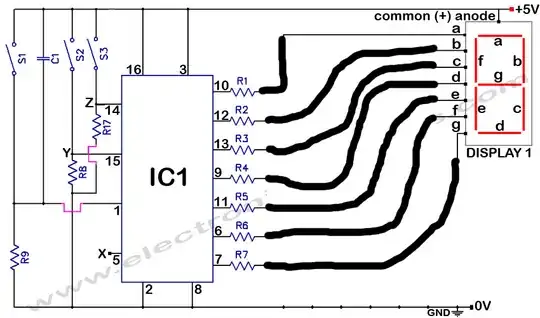
  1. Can I still use only one current limiting resistor on the common pin? Instead of a resistor on every segment pin.
  2. Can I use the pins from arduino to drive it (withouth pull-up/pull-down?) By making the signal LOW the current will flow from 5V common anode to the arduino and thus the segment wil light?
  3. Can I still use a shift register to drive the segment led? (By inversing the outputs (in software))

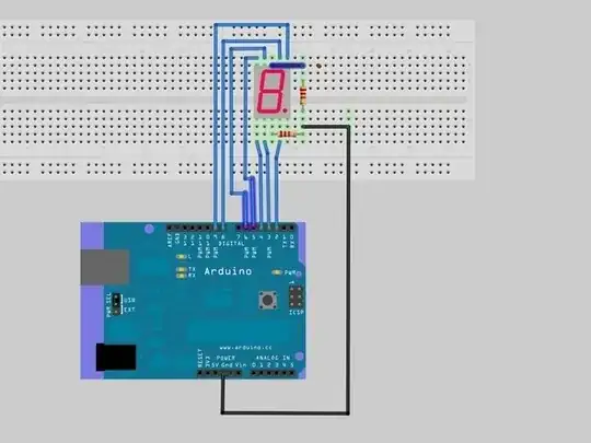
Obviously I would like to have wiring more like this (but then I would ofcourse change the GND line to a 5V line.

Better wiring


The wiring below is the worst-case wiring I can think of.

Wiring

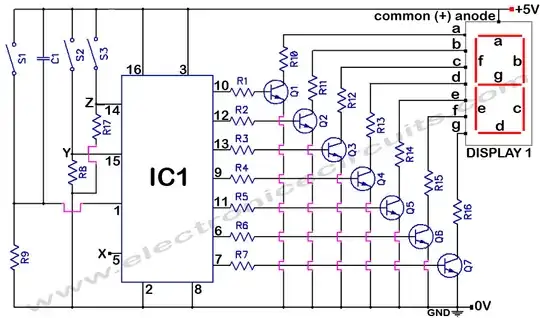
^ So can I avoid this, when using a Common Anode 7-segment display or am I forced to buy a Common Cathode 7-segment display?

aaa
  • 2,715
  • 2
  • 25
  • 40

3 Answers3

4

Sorry about the crudity of my image, but you don't always need those transistors. Peter has already said so, but I wanted to explain a bit further. schematic

The only thing is that you need to set a pin to LOW to light up the led, and HIGH to turn it off. Just use a ! to make your code more intuitive if your like. So e.g. digitalWrite(segmentA, !HIGH)

Some limitations. A pin can sink up to 40mA (no problem here), but the total sink current for the digital pins 0 to 4 shouldn't exceed 100mA. The same goes for pins 5 to 13. And the same goes for the analog pins. So either limit the current through the leds to around 10mA, or make sure no more than 5 leds are lit at the same time, or connect half of the segments to on of the above mentioned groups, and the other half another (f.y.i. analog pins can be used just like digital pins).

Gerben
  • 11,332
  • 3
  • 22
  • 34
3

You can use a single resistor on the common pin if you want. The problem is that lighting up multiple segments at the same time will substantially reduce the brightness of each one. You could work around that by lighting each segment one at a time in very quick succession though.

It should be possible to control the display directly from the IO pins by setting them LOW. In this configuration, they will be sinking current (rather than sourcing it). It depends on the specification of the display and on what resistor you use though.

Basically, try to keep the current below 20mA and it should be OK (assuming you're using a standard 5V Arduino). For example, if each segment has a forward voltage drop of 2V, you would want to use a resistor of around 180 Ohm.

Controlling the display directly from a shift register is probably not possible, although once again it depends on its specification. Shift registers usually aren't designed to sink enough current so you'll need something like a transistor on each output.

Peter Bloomfield
  • 10,982
  • 9
  • 48
  • 87
1

Peter and Gerben have already said what is needed , but I wish to explain things even further.

A normal small 7-Segment display consumes only 70-80mA when all segments are HIGH.So you can use the Arduino directly without damaging it. Also note, depending on the quality of the project, you could either use a common resistor for all segments, or use separate ones. Separate ones will give much brighter light and better quality.
A medium size one will require max consumption of around 400mA current, so use cheap transistors.
A large size one will require max consumption of upto 1.5-2A current , so use MOSFETS or other high current Transistors.
An Extra Large one will require max consumption of upto 10-25A current, so use good MOSFETS or maybe even Relays.

Usage
Small- Wrist watches
Medium- Small clocks
Large- Big clocks
Extra Large- Very big clocks like ones in Railway stations

Mathsman 100
  • 339
  • 1
  • 11