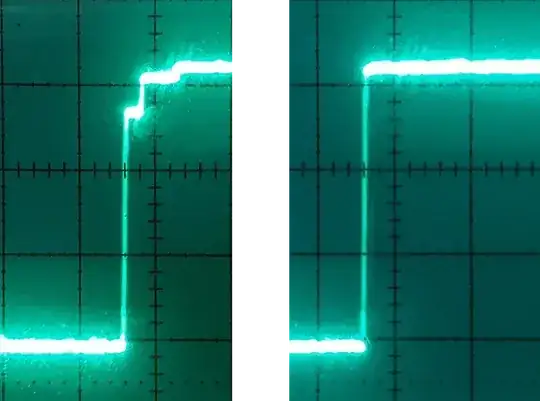
I think I've replicated the problem and somewhat mitigated it:
You might be able to mess with the GCLK_DAC.
But changing the DAC output current through DAC->DACCTRL[dac_channel].bit.CCTRL seems to be an option.
The datasheet has a table like this.
| Value |
Name |
Description |
| 0x0 |
CC100K |
GCLK_DAC ≤ 1.2MHz (100kSPS) |
| 0x1 |
CC1M |
1.2MHz < GCLK_DAC ≤ 6MHz (500kSPS |
| 0x2 |
CC12M |
6MHz < GCLK_DAC ≤ 12MHz (1MSPS) |
I printed out the default under the Adafruit samd51 support, and it reported as CC100K.
Code to change the setting:
// dac-current.h
#include "sam.h"
enum class dac_current_setting : unsigned {
  CC100K  = DAC_DACCTRL_CCTRL_CC100K_Val,  // 0  macros defined
  CC1M    = DAC_DACCTRL_CCTRL_CC1M_Val,    // 1  by the atmel dac cmsis component header
  CC12M   = DAC_DACCTRL_CCTRL_CC12M_Val,   // 2
};
inline const char *dac_current_setting_str(
  const dac_current_setting setting
) {
  switch (setting) {
    case dac_current_setting::CC100K: return "CC100K";
    case dac_current_setting::CC1M  : return "CC1M";
    case dac_current_setting::CC12M : return "CC12M";
  }
  return "unknown";
}
inline void set_dac_output_current(
  const size_t dac_channel,
  dac_current_setting new_setting
) {
  if (dac_channel >= 2) {
      abort();
  }
while (DAC->SYNCBUSY.bit.ENABLE || DAC->SYNCBUSY.bit.SWRST);
  DAC->CTRLA.bit.ENABLE = 0;
  while (DAC->SYNCBUSY.bit.ENABLE);
DAC->DACCTRL[dac_channel].bit.CCTRL = static_cast<unsigned>(new_setting);
DAC->CTRLA.bit.ENABLE = 1;
  while (DAC->SYNCBUSY.bit.ENABLE);
}
Your code modified to allow the setting to be changed live by entering digits 0, 1, and 2:
#include "dac-current.h"
void set_and_report_setting(dac_current_setting new_setting) {
  set_dac_output_current(0, new_setting);
  Serial.print("CHANGED DAC->DACCTRL[0].bit.CCTRL to ");
  Serial.print(dac_current_setting_str(new_setting));
  Serial.println();
}
void await_serial_connection() {while(!Serial);}
void setup() {
  Serial.begin(9600);
  await_serial_connection();
// Start out with high current.
  set_and_report_setting(dac_current_setting::CC12M);
  analogWriteResolution(12);
}
void loop() {
  const int c = Serial.read(); // enter 0, 1, or 2 to change current mode
  if (c >= '0' && c <= '2') {
    const auto new_setting = static_cast<dac_current_setting>(c - '0');
    set_and_report_setting(new_setting);
  }
analogWrite(A0, 0);
  delay(1);
  analogWrite(A0, 4095);
  delay(1);
}
Default DAC clock rate
I'll figure out how to make sure that the DAC clock is 12 MHz.
The Adafruit SAMD51 board package apparently has already configured this for 12 MHz. So, it does seem strange that they're also using CC100K. In short they are taking the 48 MHz DPLL and dividing that by 4. There doesn't appear to be any further division of the clock, besides the by-12 division for TCONV.
But if you don't want to take my word for it, here's code to dump relevant clock configuration information (most of these names come from the samd51 CMSIS component/gclk.h:
auto &S = Serial; //to shorten code block
//
// Constants
//
S.print("DAC_GCLK_ID              : ");

S.println(DAC_GCLK_ID, DEC);
S.print("GCLK_GENCTRL_SRC_DFLL_Val: ");
S.println(GCLK_GENCTRL_SRC_DFLL_Val, DEC);
S.println();
//
// Relevant PCHCTRL
//
const auto &p/chctrl/ = GCLK->PCHCTRL[DAC_GCLK_ID];
S.print("<pchctrl>.bit.CHEN  : "); S.println(p.bit.CHEN  , DEC);
S.print("<pchctrl>.bit.GEN   : "); S.println(p.bit.GEN   , DEC);
S.println();
//
// Relevant GENCTRL
//
const auto &g/enctrl/ = GCLK->GENCTRL[p.bit.GEN];
S.print("<genctrl>.bit.GENEN : "); S.println(g.bit.GENEN , DEC);
S.print("<genctrl>.bit.SRC   : "); S.println(g.bit.SRC   , DEC);
S.print("<genctrl>.bit.DIVSEL: "); S.println(g.bit.DIVSEL, DEC);
S.print("<genctrl>.bit.DIV   : "); S.println(g.bit.DIV   , DEC);
S.println();
Annotated output:
DAC_GCLK_ID              : 42
GCLK_GENCTRL_SRC_DFLL_Val: 6  // 48 MHz DPLL GENCLK SRC VALUE
<pchctrl>.bit.CHEN  : 1 // DAC peripheral clock is enabled
<pchctrl>.bit.GEN   : 4 // is connected to general clock index 4
<genctrl>.bit.GENEN : 1 // general clock is enabled
<genctrl>.bit.SRC   : 6 // (GCLK_GENCTRL_SRC_DFLL_Val) is derived from 48Mhz DPLL
<genctrl>.bit.DIVSEL: 0 // interpret .DIV below as simple division
<genctrl>.bit.DIV   : 4 // divide by 4; 48 Mhz / 4 == 12 MHz.
Now, you could go further and prove to yourself that the 48 MHz PLL is really running at 48 MHz... I suppose. But, it's not going to be running faster. An I'll just tell you flatly that it is being used to derive timing for the USB peripheral and is necessarily 48 MHz. But if you want to prove that you can use the same techniques.


