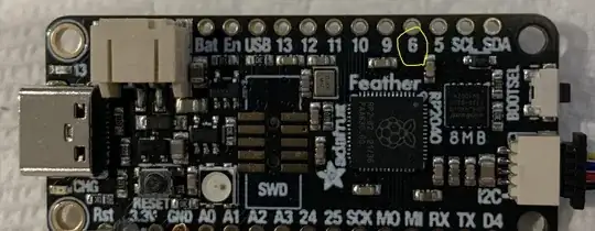
I have an Adafruit Feather RP2040 (pinouts) connected via pin 6 to a relay. The code (below) triggers the relay when a separate color sensor returns "enough" red values.
The color sensor works (confirmed by the serial print statements); the on-board LED (connected internally to pin 13) lights up when it should; but I don't get any voltage on pin 6 when I should. I'm testing the voltage with a standard multimeter. If I move my connecting wire from pin 6 to pin 13, I get voltage (and the relay activates). Why doesn't pin 6 get voltage? What else can I do to diagnose the issue?
Software versions:
- Arduino.CC IDE v2.2.1 (latest)
- Arduino IDE Board manager: added https://github.com/earlephilhower/arduino-pico, version 3.6.0 (latest)
- Adafruit APDS9960 Library from https://github.com/adafruit/Adafruit_APDS9960, version 1.2.3, released Jan 30 of this year. According to https://github.com/adafruit/Adafruit_APDS9960/tags there is a version 1.2.4 released on May 12th, but since this is just the light sensor code, which is behaving correctly, I don't believe the issue lies here.
Code:
// copied & modified from the source at:
// https://github.com/adafruit/Adafruit_APDS9960/blob/master/examples/color_sensor/color_sensor.ino
#include "Adafruit_APDS9960.h"
Adafruit_APDS9960 apds;
// the pin on the feather that we're using to talk to the relay
#define PIN_TO_RELAY 6
#define BUCKET_FULL_RED 50
void setup() {
  // enable Serial communication
  Serial.begin(115200);
// try to start the color sensor
  if(!apds.begin()) {
    Serial.println("failed to initialize device! Please check your wiring.");
  }
  else {
    // Assume success
    // Serial.println("Device initialized!");
// we want color readings
apds.enableColor(true);

}
// define the relay pin as an OUTPUT pin
  pinMode(PIN_TO_RELAY, OUTPUT);
  // start with the relay "open" AKA not running the pump
  digitalWrite(PIN_TO_RELAY, LOW);
// use the built-in LED as an external signal for "pumping"
  pinMode(LED_BUILTIN, OUTPUT);
}
void loop() {
  // create some variables to store the color data in; unused, except for 'red'
  uint16_t red, green, blue, clear;
// for checking the relay pin state
  int relay_pin_state = 0;
// for extra printing
  int debug = 1;
// wait for color data to be ready
  while (!apds.colorDataReady()) {
    delay(5);
  }
  // get fresh data; we only care about the red, but we have to read them all
  apds.getColorData(&red, &green, &blue, &clear);
if (debug) {
    Serial.print("current red value is:"); Serial.println(red);
  }
if (debug > 2) {
    relay_pin_state = digitalRead(PIN_TO_RELAY);
    if (relay_pin_state == HIGH) {
      Serial.println("steadystate: Relay pin is HIGH / enabled");
    } else {
      Serial.println("steadystate: Relay pin is LOW / disabled");
    }
  }
if (red > BUCKET_FULL_RED) {
    if (debug) {
      Serial.println("start the pump (for 5 sec)");
    }
// light up the built-in LED
digitalWrite(LED_BUILTIN, HIGH);
// "close" the relay to turn on the pump
digitalWrite(PIN_TO_RELAY, HIGH);

if (debug > 2) {
  relay_pin_state = digitalRead(PIN_TO_RELAY);
  if (relay_pin_state == HIGH) {
    Serial.println("pumping: Relay pin is HIGH / enabled");
  } else {
    Serial.println("pumping: Relay pin is LOW / disabled");
  }
}

// wait for a while for the pump to do its work
// 5 sec in ms; TODO: eventually circa 4 min
delay(5 * 1000);

if (debug) {
  Serial.println("stop the pump");
}

// turn off the built-in LED
digitalWrite(LED_BUILTIN, LOW);
// "open" the relay to turn off the pump
digitalWrite(PIN_TO_RELAY, LOW);

}
  // no need to cycle quickly; wait 1 sec in ms
  delay(1 * 1000);
}
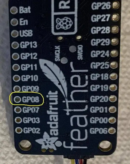
I just looked more closely at the pinouts page again, and was surprised to see the hole labeled "6" on the front is labeled "GP08" on the back, which corresponds to "GPIO8" in https://learn.adafruit.com/assets/107203. I wonder if I'm sending the "D4" pin HIGH ("GPIO6") instead of the one I'm expecting.

