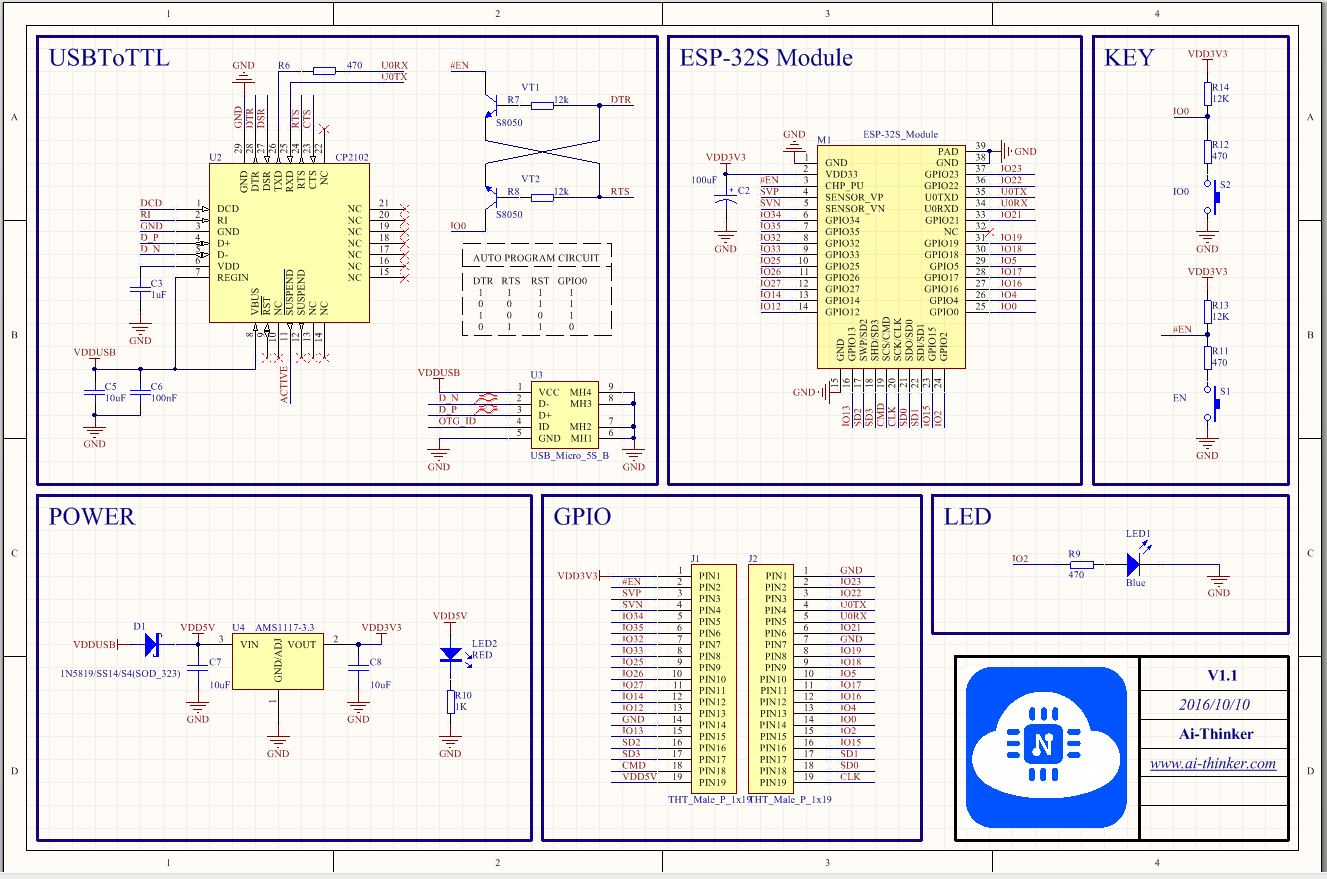
I am trying to use an esp32 (NodeMCU-32s) as a ringlight controller for my camera. All it should do is sense when an input pin goes low (the camera's output connects to ground when the shutter goes off) which is easy to detect with a simple digitalRead(). If low, then it raises 6 pins with digitalWrite() which are connected to transistors which let current flow from a 24v power supply and light up 6 banks of white LEDs. This entire setup was working great on an esp32wroom I bought from our school's shop - like I said it is very simple - but after ordering more esp32's online, I was greeted with slightly different looking ones that don't behave the same even when running the exact same code. Yes, I have verified that the pinout is the same on these two boards, although the footprint of the online boards (best datasheet I could find linked above) is one breadboard slot thinner.
Expected behavior:
I power it on, and nothing should happen until I connect pin 14 to ground, then the lights should turn on for a tenth of a second, then back off.
Actual Behavior:
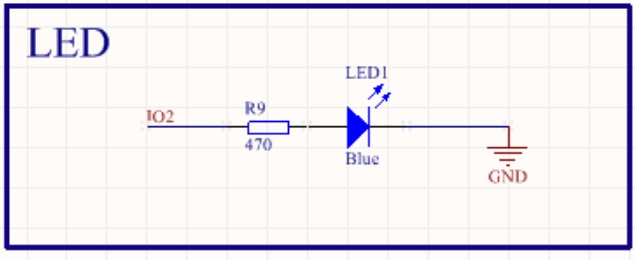
I power it on, 3 banks of lights turn on rather dimmly. The other three stay off. When I connect pin 14 to ground, the three that were off turn on for a tenth of a second, then back off. While they are on, a blue light on the nodemcu-32s dev board turns on as well...
I did some digging:
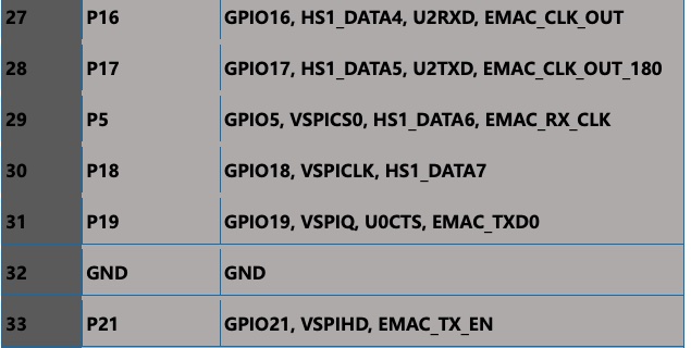
On this random nerd tutorials website I found code that identifies which pins are your board's default SPI pins and when I ran it, I found that 3 of the 6 pins I was currently using (pins 23, 19, and 5) are SPI-related ones. These were in fact the pins that behaved correctly (they were off until 14 was pulled low.)
I am not sure if this is related to the root cause of my issue or not, but it seems suspicious. Any tips from you wise arduino wizards would be appreciated - this was supposed to be simple!
Code:
Below is the code I am using. You can ignore the rgb LED stuff (LED_PIN, NUM_LEDS, BRIGHTNESS, etc.) All that matters for what I am trying to get working here are the led banks connected to pins 23, 21, 19, 5, 16, and 2. I intentionally avoided pins 6-11 because many sites were saying to avoid them.
#include <Adafruit_NeoPixel.h>
#define LED_PIN 15      // Pin connected to the Data Input of WS2812B
#define NUM_LEDS 24     // Number of WS2812B LEDs in the strip
#define BRIGHTNESS 200  // Set the brightness (0-255)
#define SHUTTER_PIN 14  //Pin connected to the shutter signal of the cameras via 3.5mm jack
Adafruit_NeoPixel strip;
void setup() {
  // setup code here, to run once:
  pinMode(23, OUTPUT); // set each bank of 6 White Leds as outputs
  pinMode(21, OUTPUT);
  pinMode(19, OUTPUT);
  pinMode(5, OUTPUT);
  pinMode(16, OUTPUT);
  pinMode(2, OUTPUT);
// set the shutterPin as a normally-high input
  pinMode(SHUTTER_PIN, INPUT_PULLUP);
// To control rgb leds
  strip = Adafruit_NeoPixel(NUM_LEDS, LED_PIN, NEO_GRB + NEO_KHZ800);
  strip.begin();
  strip.setBrightness(BRIGHTNESS);
  strip.show();
// Initialize all pixels to off
  digitalWrite(23, LOW);
  digitalWrite(21, LOW);
  digitalWrite(19, LOW);
  digitalWrite(5, LOW);
  digitalWrite(16, LOW);
  digitalWrite(2, LOW);
}
void loop() {
  //main code here, to run repeatedly:
  // if the shutter signal drops, flash on and off
  if (digitalRead(SHUTTER_PIN) == 0) {
    digitalWrite(23, HIGH);
    digitalWrite(21, HIGH);
    digitalWrite(19, HIGH);
    digitalWrite(5, HIGH);
    digitalWrite(16, HIGH);
    digitalWrite(2, HIGH);
    delay(500);
    digitalWrite(23, LOW);
    digitalWrite(21, LOW);
    digitalWrite(19, LOW);
    digitalWrite(5, LOW);
    digitalWrite(16, LOW);
    digitalWrite(2, LOW);
    delay(500);
  }
}