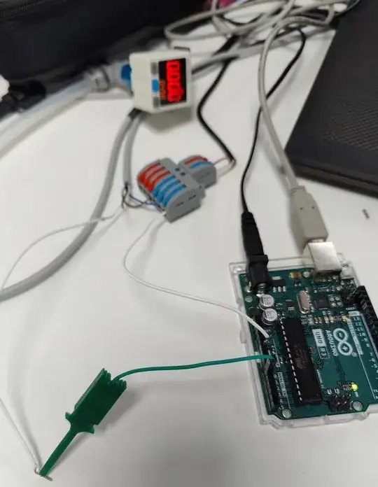
I'm trying to build a pressure data logger using an Arduino and Mindman MP47P-03-F1 (https://www.mindman.com.tw/proimages/pdf/E_MP47_S.pdf) pressure sensor, the sensor is connected to an outer 12-24 VDC power source. I've connected the analog wire to the the Arduino's A0 and added another wire from the GND to the sensor. I get a stable voltage (~1V) reading but the pressure is wrong and it doesn't respond to pressure changes. Can someone tell me what I'm doing wrong? this is the sample code:
const int analogPin = A0;
const float slope = -0.1;
const float intercept = 0.6;
const unsigned long startTime = millis();
void setup() {
  Serial.begin(9600);
  Serial.println("Time (s)\t\tPressure (MPa)");
}
void loop() {
  unsigned long elapsedTime = millis() - startTime;
  int sensorValue = analogRead(analogPin);
  float voltage = sensorValue * (5.0 / 1023.0);

  float pressure = slope * (voltage - intercept);
Serial.println(sensorValue);
  Serial.print(elapsedTime / 1000.0);
  Serial.print("\t\t");
  Serial.println(pressure);
delay(1000);
}
edit: i've changed the code to as suggested by some on the arduino forum:
const int sensorPin = A0;
const int offset = 201; // zero pressure adjust
const int fullScale = 1023; // max pressure adjust
float sensorType = 1000.0; // kPa
float pressure; // final pressure
const unsigned long startTime = millis();
void setup() {
  Serial.begin(9600);
}
void loop() {
  unsigned long elapsedTime = millis() - startTime;
  pressure = (analogRead(sensorPin) - offset) * sensorType / (fullScale - offset);
Serial.print(analogRead(sensorPin));
  Serial.print("\t\t");
  Serial.print(elapsedTime / 1000.0);

  Serial.print("\t\t");
  Serial.println(pressure, 4);
  delay(1000);
}
the pressure is 0 but i keep getting jumps in the readings of the pressure when no pressure is applied. here is the picture of the wiring. 