1

I am trying to understand this rotary encoder I have, but it makes no sense to me.

I am using this rotary encoder: https://www.amazon.com/gp/product/B07DM2YMT4/

CYT1100 aka CY110 aka EC11

I am using this wiring: https://i.sstatic.net/aMyR5.png

P2 is the "push button" and it gives continuity when pressed.

I am using a knock off arduino nano and this is my simple script:

#define PIN_CLK 2

void setup() { Serial.begin(9600); pinMode(PIN_CLK, INPUT); }

void loop() { auto val = digitalRead(PIN_CLK);

Serial.println("CLK:" + String(val));

}

Where PIN_CLK is connected to A (DW) or B (CLK) in the diagram.

My expectation is that A and B should be either a constant HIGH or LOW depending on where the brushes are internally. Not switching to HIGH or LOW for a moment and then returning to what it was before.

When I check them with my multimeter, they are both always 5v (when its not making loose contact on the breadboard).

The serial plotter says its switching between HIGH and LOW repeated:

https://i.sstatic.net/6VC3z.png

Same with the Serial monitor:

https://i.sstatic.net/wAk0v.png

When I spin the encoder, it gives me gaps of LOW in the output like this:

https://i.sstatic.net/lOUmx.png

If I hold my index and thumb against P1 (5v) and A (CLK) while spinning the encoder. I get constant stream of HIGH with a LOW on every notch spin:

https://i.sstatic.net/CzUwV.png

Can someone explain this behavior and how this encoder is suppose to work?

Edit: I tried this schematic:

https://i.sstatic.net/Mlj1l.png

Whenever I turn the encoder. The LED blinks for a few milliseconds. Then turns off.

Is it suppose to stay solid depending on the 2 bit states?

Edit2: If I turn it extremely slowly. It turns the leds on in the order of left right or right left depending on the direction.

So the led diagram above works, but its weird to me.
John
  • 123
  • 4

2 Answers2

3

There are several problems happening here. Since your code only covers one input pin, I'm going to talk about input A. This pin is left floating! When you turn the dial, the brush connects A and/or B to G in your photo, or in other words, pins A/B to ground. But if A/B is not connected to ground, there is no other voltage state - it's just left floating. You need to have a logic LOW 0V and a logic HIGH (either 3.3V or 5V depending on your Arduino board) for the Arduino to be able to distinguish between the LOW and HIGH states. You can solve this by changing your code to:

pinMode(PIN_CLK, INPUT_PULLUP);

This way when the pin (A) is not connected to GND via (G), it is held at a logic HIGH state.

P1 & P2 are the for the button, so you can't ignore one of the pins. To wire that correctly using an input pullup, P1 needs to connect to GND. P2 needs to connect to an input pin with another input_pullup. When the button is unpressed, the state will default to HIGH. When it's pressed, it will be connected to GND and show as LOW.

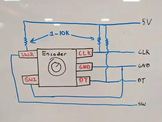
You are most likely following the images online for wiring the encoders that are already on a PCB. That PCB has 3 pullup resistors on it. Regardless if you are using code to do it or hardware, the circuit needs to look like this. input_pullup on the Arduino will act just like resistors shown in the circuit.

Here is a great resource: https://lastminuteengineers.com/rotary-encoder-arduino-tutorial/

enter image description here

AJ_Smoothie
  • 504
  • 4
  • 13
1

When encountering weird values from a rotary encoder, there are a few possible reasons and troubleshooting steps you can take:

Mechanical issues: Check if there is any physical damage or obstruction affecting the rotary encoder's movement. Ensure that it rotates smoothly without any unusual resistance or skips.

Loose connections: Verify the wiring connections between the rotary encoder and the device it is connected to. Ensure that the connections are secure and properly seated.

Electrical noise: Electrical noise or interference can sometimes cause erratic readings. Try using shielded cables for the connections and consider adding capacitors or ferrite beads to filter out noise.

Incorrect configuration: Review the setup and configuration of the rotary encoder in your code or software. Make sure that you have selected the correct type of encoder (incremental or absolute) and that the signal processing is correctly implemented.

Debouncing: If you are using an incremental rotary encoder, it may produce multiple pulses or bouncing signals when rotating. Implementing debouncing techniques in your code can help filter out these erroneous readings.

Resolution and speed settings: Check if the resolution and speed settings in your code or software match the specifications of your rotary encoder. Incorrect settings can lead to unexpected values.

Compatibility issues: Ensure that the rotary encoder you are using is compatible with the device or system you are connecting it to. Check the specifications and requirements of both the encoder and the device to ensure compatibility.

If you have gone through these troubleshooting steps and are still experiencing weird values from your rotary encoder, it might be worth considering a replacement or consulting the manufacturer's support for further assistance.