I want to make a 10 channels Arduino mega-based battery capacity tester using 4.7 ohms 10w resistors controlling them with IRFZ44n MOSFETs with respected digital pins. An 8.4V battery powers the Arduino (do not consider the buck converter in the picture). I am debugging my project step by step. When I read voltages of individual batteries by corresponding analog pins without turning On 'MOSFET-Gate pins' then Arduino measures the voltages correctly but when I turn on the gate pins then Arduino measures voltage incorrectly. Meaning if I connect a battery with an analog pin and a multimeter at the same time and the value is pretty much same. Like 3.70 volt for the multimeter and 3.72 for analog pin but when I turn On the gatepin of the MOSFET then Arduino value is like 3.07V and Multimeter value is 3.48V. Thanks in advance.
Here is the Circuit Diagram of my project:

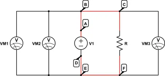
Simple version to understand:

Code:
long readVcc() {
   // Read 1.1V reference against AVcc
   // set the reference to Vcc and the measurement to the internal 1.1V reference
#if defined(__AVR_ATmega32U4__) || defined(__AVR_ATmega1280__) || defined(__AVR_ATmega2560__)
   ADMUX = _BV(REFS0) | _BV(MUX4) | _BV(MUX3) | _BV(MUX2) | _BV(MUX1);
#elif defined (__AVR_ATtiny24__) || defined(__AVR_ATtiny44__) || defined(__AVR_ATtiny84__)
   ADMUX = _BV(MUX5) | _BV(MUX0) ;
#else
   ADMUX = _BV(REFS0) | _BV(MUX3) | _BV(MUX2) | _BV(MUX1);
#endif
   ADCSRB &= ~_BV(MUX5);
   delay(2); // Wait for Vref to settle
   ADCSRA |= _BV(ADSC); // Start conversion
   while (bit_is_set(ADCSRA,ADSC)); // measuring
uint8_t low  = ADCL; // must read ADCL first - it then locks ADCH
   uint8_t high = ADCH; // unlocks both
long result = (high<<8) | low;
result = 1125300L / result; // Calculate Vcc (in mV); 1125300 = 1.110231000   //1126400L internalRefVolt(1.1) * 1023 * 1000; code can more precse by calculating internalRefVolt(1.1)
   return result; // Vcc in millivolts
}
void setup() {
   Serial.begin(115200);
   delay(3000);
   pinMode(22,OUTPUT);//*Mosfet Gate Pins******
   pinMode(23,OUTPUT);
   pinMode(24,OUTPUT);
   pinMode(25,OUTPUT);
   pinMode(26,OUTPUT);
   pinMode(27,OUTPUT);
   pinMode(28,OUTPUT);
   pinMode(29,OUTPUT);
   pinMode(30,OUTPUT);
   pinMode(31,OUTPUT);
digitalWrite(22,LOW);//*Initially low the Mosfet Gate Pins******
   digitalWrite(23,LOW);
   digitalWrite(24,LOW);
   digitalWrite(25,LOW);
   digitalWrite(26,LOW);
   digitalWrite(27,LOW);
   digitalWrite(28,LOW);
   digitalWrite(29,LOW);
   digitalWrite(30,LOW);
   digitalWrite(31,LOW);
}
/********************************Void Loop****************************************************/
void loop() {
   float voltRef = readVcc() / 1000.0;
digitalWrite(22,HIGH);//*** High the Mosfet Gate Pins********
   digitalWrite(23,HIGH);
   digitalWrite(24,HIGH);
   digitalWrite(25,HIGH);
   digitalWrite(26,HIGH);
   digitalWrite(27,HIGH);
   digitalWrite(28,HIGH);
   digitalWrite(29,HIGH);
   digitalWrite(30,HIGH);
   digitalWrite(31,HIGH);
float volt0 = analogRead(A0)(voltRef/1024);
   delay(10);
   volt0 = analogRead(A0)(voltRef/1024);
   /* if(volt0>3.0){
      digitalWrite(22,HIGH); // High = Mosfet ON
      digitalWrite(36,HIGH); // High = LED Turn OFF
  }*/


float volt1 = analogRead(A1)(voltRef/1024);
   delay(10);
   volt1 = analogRead(A1)(voltRef/1024);
float volt2 = analogRead(A2)(voltRef/1024);
   delay(10);
   volt2 = analogRead(A2)(voltRef/1024);
float volt3 = analogRead(A3)(voltRef/1024);
   delay(10);
   volt3 = analogRead(A3)(voltRef/1024);
float volt4 = analogRead(A4)(voltRef/1024);
   delay(10);
   volt4 = analogRead(A4)(voltRef/1024);
float volt5 = analogRead(A5)(voltRef/1024);
   delay(10);
   volt5 = analogRead(A5)(voltRef/1024);
float volt6 = analogRead(A6)(voltRef/1024);
   delay(10);
   volt6 = analogRead(A6)(voltRef/1024);
float volt7 = analogRead(A7)(voltRef/1024);
   delay(10);
   volt7 = analogRead(A7)(voltRef/1024);
float volt8 = analogRead(A8)(voltRef/1024);
   delay(10);
   volt8 = analogRead(A8)(voltRef/1024);
float volt9 = analogRead(A9)(4.95/1024);
   delay(10);
   volt9 = analogRead(A9)(4.95/1024);
//*****************************************************************************
   Serial.print("B0= ");
   Serial.println(volt0);
Serial.print("B1= ");
   Serial.println(volt1);
Serial.print("B2= ");
   Serial.println(volt2);
Serial.print("B3= ");
   Serial.println(volt3);
Serial.print("B4= ");
   Serial.println(volt4);
Serial.print("B5= ");
   Serial.println(volt5);
Serial.print("B6= ");
   Serial.println(volt6);
Serial.print("B7= ");
   Serial.println(volt7);
Serial.print("B8= ");
   Serial.println(volt8);
Serial.print("B9= ");
   Serial.println(volt9);
Serial.println("");
   Serial.println("==========================");
   delay(500);
}