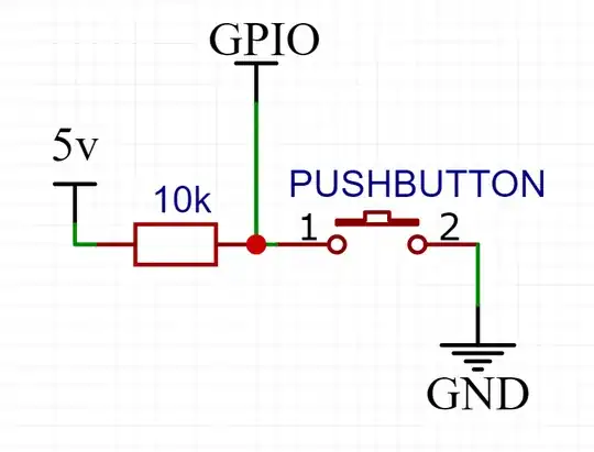
I have a circuit which consists of a pushbutton and 2 relays.
The power supply is driven either over USB, where the circuit seems to work fine, or powered by a linear regulator board I've knocked together consisting of an LM78XX (see the next paragraph for detail), where the circuit exhibits the behaviour.
Detail of power supply:
The LM7808 was used to drive the main voltage into the Nano, via the VIN pin. It is supported by a 330n and 100n capacitor, as per the standard circuit diagrams for LM78XX chips. The LM7805 was also used to drive the nano via the 5v pin, as well as the Pico via its 5v pin. Using LM7805, I drove the 5v relay boards directly from the power supply, not utilising the onboard 5v regulator. Using the LM7808, I used the onboard 5v regulator to power the relay boards since they required 5v, not 8v. I have tried each of these configurations with no success.
I have 2 relay boards, each has 5v, GND, and IN. These take their 5v and GND directly from the same power supply driving the Arduino where possible, or from the regulator on the board where necessary (when powered by 8v).
On power up, the relays go to opposing states (one switches on, the other stays off).
I also have essentially a pushbutton, which currently consists of a choc block that I short out with a piece of wire by hand. I have had it pulled up by the Arduino, and shorting it to ground with the pushbutton. I have also had it pulled up manually, with a 10k resistor as per the circuit diagram below. In all configurations, note that it was a choc block and a piece of wire.
Now, for the unexpected behaviour. When I power this circuit over USB, the pushbutton works almost entirely. I may have seen it fail once or twice, I can't be sure. It seems to behave as expected 99% of the time. When I power it from a 12v power supply (into the LM78XX regulator) however, I only need to wave my hand near the choc block of the "pushbutton" and it will fire. Sometimes it will fire for seemingly no reason at all, other times I will need to connect a small length of wire only to the GPIO side of the choc block and it will fire the switch.
My current code is as below:
const int signal_1 = 10;
const int relay_1 = 11;
const int relay_2 = 12;
bool state = false;
void setup() {
  // put your setup code here, to run once:
  pinMode(relay_1, OUTPUT);
  pinMode(relay_2, OUTPUT);
  pinMode(signal_1, INPUT_PULLUP);
digitalWrite(relay_1, LOW);
  digitalWrite(relay_2, HIGH);
}
void toggleRelays() {
  digitalWrite(relay_1, !state);
  delay(5000);
  digitalWrite(relay_2, state);
  state = !state;
}
void loop() {
  // put your main code here, to run repeatedly:
  int sensor_1_val = digitalRead(signal_1);
if (sensor_1_val == LOW) {
    toggleRelays();
  }
}
I have simplified this as much as possible, and tried it in as many variations as I can think of. I still suffer from this interference issue.
Can anyone explain what might be happening here? Is it possible that I'm suffering from a brownout, and need to add an additional capacitor on the power supply? Is there something I'm obviously missing about the switch circuit?
