I'm an art student and absolute beginner to electronics/code - my broader goal is to learn how to control individual LEDs when there are many of them (like 64 or more even, so am learning about shift registers, multiplexing etc. also).
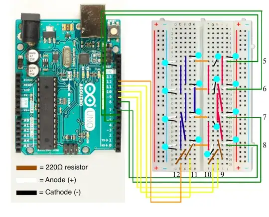
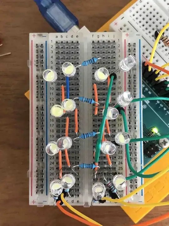
I have been working with a 4x4 matrix example by Jon Fox. I have breadboarded it as below and checked it multiple times.
For the most part it's successful; the code runs and I get the LED animations in his code. I am also able to anticipate which parts of the code refer to which LEDs when I test by commenting out parts of the code - for example r1c1() refers to the top row, right-most LED.
However, the top row, second from the left LED does not turn on.
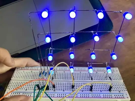
I have tested the individual LEDs before starting, tested the connections of the wires in case they don't make good connection in the breadboard, and tried adding 330 Ω resistors to the rows (instead of the orange connection wire in the image), and tried with 1 kΩ resistors instead of 220 Ω. The reason I tried those values was that I have been successful when I've used another set up I have, image below.
The blue and the white LEDs draw similar voltage so as far as I understand this wouldn't affect anything. The code runs great on this also.
I understand I could still be making some human error, especially as I've been going crazy with this. However, because I really want to understand the factors involved in controlling LEDs, I'd love to know if at all there are other variables at play.
For one, I was looking into 'floating inputs' hence tried adding the other set of resistors, and tried colour LEDs (more bulbs were either off or dim) as well as 3 mm white LEDs (same result as 5mm). The most difficult thing in this process is wondering what I don't know, so if anyone can direct me towards things I should consider for my purpose, or help me solve my current problem, I'd be really grateful.


