Problem description
When XIAO microcontroller is connected to the sensor signal output pin, keep printing unexpected values.
Sketch

 I haven't sensor circuit diagram, you can machine translate and read the pagehttps://www.yuque.com/cs/products/rwe87o
Detailed description:
The sensor has been outputting a raw value of about 4000. That is to say, the transformation of the function outputs is around 1600000~400000. Not the 0 to 30 values I expected to output.(I tried to use other development board ESP32 to read the sensor value using ADC and its own power supply pin, and still output the original value of 4000(output 1600000~400000), as shown in the figure below.)
Abnormal output

Normal output:

This is the output I expect, but I can't reproduce the normal output (last month was very occasionally normal output, I don't know why it can't normal output now and the environment has not changed...Analog circuits are too much like witchcraft...)
I try to do:
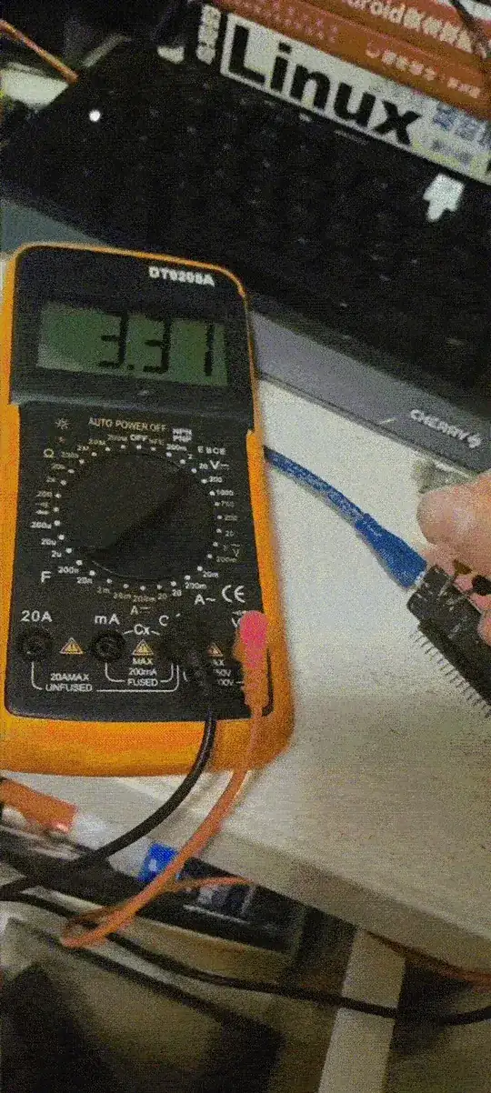
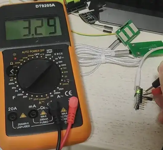
- Measured with a digital multimeter to ESP32 and XIAO, the power supply pin(to measure voltage between 3.3V and GND pin) is about 3.1V~3.3V(maybe my positive and negative probes are not accurate).
Check XIAO's ADC using ADC pin to GND pin for any problems with Analog pins read GND and VCC respectively, with 12bit resolution and output of 100 and 4000 + respectively.XIAO is fine.
The Sensor connects the
TTL to USBpower supply pin, but the output is still abnormal.(I used PWM pin by esp32 or xiao MCU to output analog 3.3V, results same to abnormal output)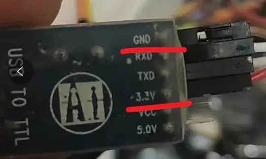
If the sensor signal output is connected to MCU, the high value of 4000 is output(The original value). Seems to be the power problem, someone tell me how to minimize the power ripple effect and make the 3.3V stable output provided by the battery? But when I unplug the sensor, the MCU outputs random values, and I don't want the sensor output to be affected by other factors.

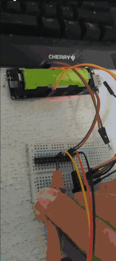
- DMM Checks the sensor output and GND pin separately, using only the DMM, sensor, 3.3V battery module, and breadboard:
(This is one 3P Dupont line and the colors are random.I didn't have a wiring error. If the wiring is wrong neither the MCU nor the sensor will work properly, let alone output signals)
 The quality of my DMM is poor, I will measure it when my FLUKE17B+ arrives.
Use MCU to read the value, sure enough, the output value is not affected by the power on or off, because the output value is more than 100000(raw value is 4000,12 bit).
other
Asked the store, customer service said this is not normal, the sensor should output the value of 0~500, if the sensor monitors the current output of 200~400, not monitoring the general output of 0~30 range.
Equipment information
XIAO EMG sampled code: EMG.ino · GitHub
Sensor parameters: {ED0056}Sensor
Microcontrollers XIAO general description: Getting Started with Seeeduino XIAO - Seeed Wiki
Microcontrollers XIAO instruction manual: https://files.seeedstudio.com/wiki/Seeeduino-XIAO/res/ATSAMD21G18A-MU-Datasheet.pdf

How do I solve XIAO’s the sensor’s abnormal output?

](https://i.sstatic.net/FzRfE.png)