I currently do most of my AVR work on breadboards, but the large variety of Arduino shields and code out there makes me wonder if I'm not beating my head against the wall sometimes, and looking up port to pin mappings both wastes time and slows me down. Is there any convenient way to adapt AVRs (other than those pin-compatible with current Arduinos) to Arduino shields?
Asked
Active
Viewed 502 times
2 Answers
4
You can make adapter boards (one for each mcu model).
The bottom side (male headers) would plug to the breadboard and the upper side would have female headers with the same pinout as an Arduino board (female hearers placed in the appropriate positions to match Arduino shields).
Such a board shouldn't be difficult to design.
Here is an image that resembles what I describe
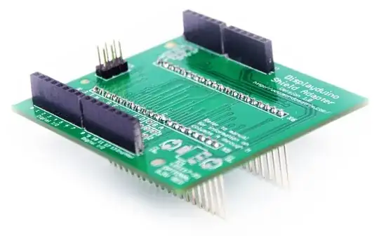
It would adapt the pinout of a bare AVR to the pinout of a typical Arduino so that shields can by directly plugged on top of it.
Also a pinout diagram may come handy to speedup things when you use a bare chip with Arduino code.
(image source)

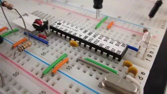
Another similar solution is a small printed sticker placed on top of the AVR
(image source)
alexan_e
- 1,860
- 1
- 13
- 16
2
The Arduino-way of doing that is making a lookup table that translates pin number to PORTn / DDRn / PINn SFR and the related bit. You can use the same trick and make GPIO pins count in a convenient way as they are in the package. Only special peripherals (like SPI / PWM) cannot be accounted for in this way because they are hard wired to a pin.
A good start is the below Arduino.h library sniplet if you want to re-use that concept.
// Get the bit location within the hardware port of the given virtual pin.
// This comes from the pins_*.c file for the active board configuration.

#define analogInPinToBit(P) (P)

// On the ATmega1280, the addresses of some of the port registers are
// greater than 255, so we can't store them in uint8_t's.
extern const uint16_t PROGMEM port_to_mode_PGM[];
extern const uint16_t PROGMEM port_to_input_PGM[];
extern const uint16_t PROGMEM port_to_output_PGM[];

extern const uint8_t PROGMEM digital_pin_to_port_PGM[];
// extern const uint8_t PROGMEM digital_pin_to_bit_PGM[];
extern const uint8_t PROGMEM digital_pin_to_bit_mask_PGM[];
extern const uint8_t PROGMEM digital_pin_to_timer_PGM[];

// Get the bit location within the hardware port of the given virtual pin.
// This comes from the pins_*.c file for the active board configuration.
//
// These perform slightly better as macros compared to inline functions
//
#define digitalPinToPort(P) ( pgm_read_byte( digital_pin_to_port_PGM + (P) ) )
#define digitalPinToBitMask(P) ( pgm_read_byte( digital_pin_to_bit_mask_PGM + (P) ) )
#define digitalPinToTimer(P) ( pgm_read_byte( digital_pin_to_timer_PGM + (P) ) )
#define analogInPinToBit(P) (P)
#define portOutputRegister(P) ( (volatile uint8_t *)( pgm_read_word( port_to_output_PGM + (P))) )
#define portInputRegister(P) ( (volatile uint8_t *)( pgm_read_word( port_to_input_PGM + (P))) )
#define portModeRegister(P) ( (volatile uint8_t *)( pgm_read_word( port_to_mode_PGM + (P))) )
The pinMode, digitalWrite and digitalRead functions are defined in /usr/share/arduino/hardware/arduino/cores/arduino/wiring_digital.c which can be used for further inspiration.
jippie
- 2,901
- 14
- 23
-
While this answer covers the software part, my question actually asks about the hardware part. – Ignacio Vazquez-Abrams Mar 24 '14 at 07:14
-
@IgnacioVazquez-Abrams can you elaborate a bit more in your question then? Not sure if I understand what you're asking. – jippie Mar 24 '14 at 07:28
-
I have bare AVR chips, and I want to use them with existing Arduino shields without having to add a couple dozen jumper wires. – Ignacio Vazquez-Abrams Mar 24 '14 at 07:56