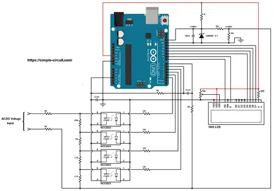
I am try to build this AC-DC meter, the code original used default A3 as input, how can change the input on A0? the link: https://simple-circuit.com/arduino-autoranging-ac-dc-voltmeter-with-trms/
Thanks for help Adam
/**************************************************************************
*
* Arduino autoranging AC/DC voltmeter.
* Voltage and frequency are printed on 1602 LCD screen.
* This is a free software with NO WARRANTY - Use it at your own risk!
* https://simple-circuit.com/
*
*************************************************************************/
#include <LiquidCrystal.h>   // include Arduino LCD library
// LCD module connections (RS, E, D4, D5, D6, D7)
LiquidCrystal lcd(8, 9, 10, 11, 12, 13);
// define autoranging channel pins
#define CH0  2
#define CH1  3
#define CH2  4
#define CH3  5
const uint16_t Time_Out = 50000,  // time out in microseconds
              Periods  = 10;     // number of periods of measurement (for AC voltage only)
// variables
byte ch_number;
const uint16_t res_table[4] = {2444, 244, 94, 47},  // voltage divider resistances in tenths kOhms
              total_res = 22444;                   // total resistance in tenths kOhms
uint16_t current_res;
volatile byte per;
void setup(void)
{
 pinMode(CH0, OUTPUT);
 pinMode(CH1, OUTPUT);
 pinMode(CH2, OUTPUT);
 pinMode(CH3, OUTPUT);
lcd.begin(16, 2);     // set up the LCD's number of columns and rows
 lcd.setCursor(1, 0);
 lcd.print("Voltage:");
ch_number = 0;
 ch_select(ch_number);
// ADC and analog comparator configuration
 ADMUX  = 0x03;
 ADCSRA = 0x87;
 ADCSRB = (0 << ACME);  // select AIN1 as comparator negative input
 ACSR   = 0x13;         // turn on analog comparator
}
// analog comparator ISR
ISR (ANALOG_COMP_vect)
{
 byte count = 0;
 for(byte i = 0; i < 50; i++) {
   if ( ACSR & 0x20 )
     count++;
 }
if(count > 48)
   per++;
}
// main loop
void loop()
{
 bool dc_flag = 0; // DC voltage flag bit
 int32_t sum = 0;  // sum of all readings
 uint16_t n = 0;   // number of readings (samples)
ACSR = (1 << ACI);   // clear analog comparator interrupt flag
 ACSR = (1 << ACIE);  // enable analog comparator interrupt
uint32_t current_m = micros();  // save current millis
 byte current_per = per;         // save current period number
 while ( (current_per == per) && (micros() - current_m < Time_Out) ) ;
if( micros() - current_m >= Time_Out ) {  // if there's time out event ==> voltage signal is DC
   dc_flag = 1;
   for (byte i = 0; i < 200; i++) {
     ADCSRA |= 1 << ADSC;   // start conversion
     while(ADCSRA & 0x40);  // wait for conversion complete
     int16_t an = (int16_t)(ADCL | (uint16_t)ADCH << 8) - 511;
     sum += an;
     n++;         // increment number of readings
     delay(1);
   }
 }
else {   // here, voltage signal is AC
   current_m = micros();  // save current millis()
   per = 0;
   while ( (per < Periods) && (micros() - current_m < (uint32_t)Time_Out * Periods) ) {
     ADCSRA |= 1 << ADSC;   // start conversion
     while(ADCSRA & 0x40);  // wait for conversion complete
     int32_t an = (int16_t)(ADCL | (uint16_t)ADCH << 8) - 511;
     sum += sq(an);  // sq: square
     n++;            // increment number of readings
   }
 }
ACSR = (0 << ACIE);  // disable analog comparator interrupt
 uint32_t total_time = micros() - current_m;  // used to claculate frequency
// voltage calculation
 float v;
 if(dc_flag)   // if voltage signal is DC
   v = (4 * sum)/n;   // calculate Arduino analog channel DC voltage in milli-Volts
else  // here voltage signal is AC
   v = 4 * sqrt(sum/n);   // calculate Arduino analog channel RMS voltage in milli-Volts
// claculate actual (input) voltage in milli-Volts (apply voltage divider equation)
 v = v * (float)total_res/current_res;
 v /= 1000;  // get voltage in Volts
uint16_t v_abs = abs(int16_t(v));
 if( (v_abs >= 10 && ch_number == 0) || (v_abs >= 100 && ch_number == 1) || (v_abs >= 250 && ch_number == 2) ) {
   ch_number++;
   ch_select(ch_number);
   delay(10);
   return;
 }
if( (v_abs < 220 && ch_number == 3) || (v_abs < 80 && ch_number == 2) || (v_abs < 8 && ch_number == 1) ) {
   ch_number--;
   ch_select(ch_number);
   delay(10);
   return;
 }
char _buffer[8];
 lcd.setCursor(0, 1);
 if( v < 0)
   lcd.print('-');
 else
   lcd.print(' ');
 if(v_abs < 10)
   sprintf( _buffer, "%01u.%02u", v_abs, abs((int16_t)(v * 100)) % 100 );
 else if( v_abs < 100)
   sprintf( _buffer, "%02u.%01u", v_abs, abs((int16_t)(v * 10)) % 10 );
 else
   sprintf( _buffer, "%03u ", v_abs );
lcd.print(_buffer);
 if(dc_flag)
   lcd.print("VDC        ");
 else {
   lcd.print("VAC ");
   // calculate signal frequency in Hz
   uint32_t period_time = total_time/Periods;
   float freq = 1000000.0/period_time;
   sprintf( _buffer, "%02u.%02uHz", (uint16_t)freq % 100, (uint16_t)(freq * 100) % 100 );
   lcd.print(_buffer);
 }
delay(500);    // wait half a second
}
void ch_select(byte n) {
 switch(n) {
   case 0:
     digitalWrite(CH0, HIGH);
     digitalWrite(CH1, LOW);
     digitalWrite(CH2, LOW);
     digitalWrite(CH3, LOW);
     break;
   case 1:
     digitalWrite(CH0, LOW);
     digitalWrite(CH1, HIGH);
     digitalWrite(CH2, LOW);
     digitalWrite(CH3, LOW);
     break;
   case 2:
     digitalWrite(CH0, LOW);
     digitalWrite(CH1, LOW);
     digitalWrite(CH2, HIGH);
     digitalWrite(CH3, LOW);
     break;
   case 3:
     digitalWrite(CH0, LOW);
     digitalWrite(CH1, LOW);
     digitalWrite(CH2, LOW);
     digitalWrite(CH3, HIGH);
 }
 current_res = res_table[n];
}
// end of code.
