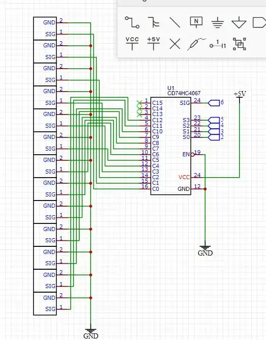
 I am working on a project with a claw machine. I am working on this chip (CD4067BE which is equivalent to the CD74HC4067) and I was wondering: can I read more than one button with the CD4067? I tried the following code, and it works great, but when I want to push two buttons, it will not read both of them as zero. Why am I using a chip with the buttons? It was to reduce I/O pins on my PCB for the claw machine. Yes, I could use a matrix, but I want control over my components, whether to turn it on or off. Also, the CD4067 includes all my buttons. I have thirteen buttons. (13 buttons). By the way, this chip is a multiplexer/demultiplexer. I am using this chip as a multiplexer. Oh, and also, I have an Arduino Mega 2560 rev3. I have followed the instructions of this question, but this doesn't answer if the chip can read more than button at one time. Thanks,
Austin
//Mux control pins
int s0 = 5;
int s1 = 4;
int s2 = 3;
int s3 = 2;
//Mux in "SIG" pin
int SIG_pin = 6;
void setup() {
pinMode(s0, OUTPUT);
  pinMode(s1, OUTPUT);
  pinMode(s2, OUTPUT);
  pinMode(s3, OUTPUT);
pinMode(SIG_pin, INPUT_PULLUP);
Serial.begin(9600);
}
void loop() {
//Loop through and read all 16 values
  for (int i = 0; i < 16; i ++) {
    Serial.print("Value at channel ");
    Serial.print(i);
    Serial.print("is : ");
    Serial.println(readMux(i));
    delay(1000);
  }
}
int readMux(int channel) {
  int controlPin[] =       {s0, s1, s2, s3};
  int muxChannel[16][4] = { {0, 0, 0, 0},
                            {1, 0, 0, 0},
                            {0, 1, 0, 0},
                            {1, 1, 0, 0},
                            {0, 0, 1, 0},
                            {1, 0, 1, 0},
                            {0, 1, 1, 0},
                            {1, 1, 1, 0},
                            {0, 0, 0, 1},
                            {1, 0, 0, 1},
                            {0, 1, 0, 1},
                            {1, 1, 0, 1},
                            {0, 0, 1, 1},
                            {1, 0, 1, 1},
                            {0, 1, 1, 1},
                            {1, 1, 1, 1}
                          };
  //loop through the 4 sig
  for (int i = 0; i < 4; i ++) {
    digitalWrite(controlPin[i], muxChannel[channel][i]);
  }
  //read the value at the SIG pin
  int val = digitalRead(SIG_pin); //return the value
  return val;
}