1

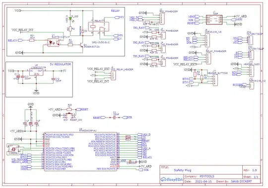
I created a custom PCB based on a 328P. The design is mainly based on the Arduino Nano schematic (3.0). The boards have arrived some days ago, and I can't get avrdude to recognize them via USBASP (or any other mean for that matter). When trying to program the board is powered via the ICSP connector. What I have tried so far:

  • only soldering the essential components: CAPs for 5V rail
  • soldering the Oscillator or leaving it off
  • on one board I even cut all lines except 5V, GND, RST and SPI.

Still the 328p won't respond, all I get is :

#avrdude -u -c usbasp -P COM1 -b 57600 -B 0.5 -p m8

WARNING: Unable to detect MCU avrdude.exe: set SCK frequency to 1500000 Hz avrdude.exe: error: program enable: target doesn't answer. 1 avrdude.exe: initialization failed, rc=-1 Double check connections and try again, or use -F to override this check. avrdude.exe done. Thank you.

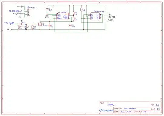
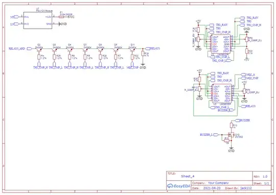
I will attach my schematics and my board design, I know it is not the cleanest for now... It is my first one and I am currently trying to clean it up/make it better. I also added 1k resistors in line to RX and TX, but they are not present in the board design for now.

I am thankful for any help and/or advice

I can provide the board design if needed:)
enter image description here

enter image description here

enter image description here

jack
  • 123
  • 3

1 Answers1

1

So you had:

SCK frequency to 1500000

And I suggested lowering to the point where you:

set it to 8k solved it:)

Good deal. The thing that you were likely running afoul of is the maximum ISP clock rate, which according to the datasheet for the ATMega328P (or practically any other AVR for that matter) is determined by some rules:

Low:> 2 CPU clock cycles for fck < 12MHz, 3 CPU clock cycles for fck ≥ 12MHz
High:> 2 CPU clock cycles for fck < 12MHz, 3 CPU clock cycles for fck ≥ 12MHz

So your maximum ISP clock rate is dependent on the chip's clock rate. And is either at most a quarter of a sixth of that, depending on whether or not the chip operating below or above 12MHz.

Most ordering codes of AVRs of the type that do this kind of ISP programming ship from the factory at on the internal 8 MHz oscillator with the divide-by-8 fuse enabled; So they're at 1 MHz with a maximum ISP clock rate of 250 kHz. Had you been working with a the typical Arduino arrangement when it had already been set up for and running with a 16 MHz clock, the 1.5 MHz ISP clock rate might have worked. I'd have still slowed it down, since it will only be more likely to work when doing that.

Most programmers default to a low clock rate, closer to your 8k figure. Usually, if people have a problem with hitting the maximum ISP clock rate, it's because they have a very low system clock, either using a watch crystal or fusing for the internal 128 kHz, or either in combination with the divide-by-8-fuse. Often when trying to go too-fast, what's holding them up is crappy wiring.

When you're programming there's a limit to how useful it is to crank the clock rate up anyway, because eventually there's going to be a lot of hurry-up-and-wait while the chip flashes sectors and the timing of that isn't dependent on the clock rate.

timemage
  • 5,639
  • 1
  • 14
  • 25