2

I want to achieve the generation of a custom binary signal over a digital pin at the highest possible frequency on Arduino Uno.

Using Timer's output pins (e.g. OC0A), one can get a pin to toggle at a maximum frequency of 16MHz (which corresponds to a sqaure wave of frequency 8MHz), as described here: Maximum frequency of digital signal in Arduino Uno?

However as far as I understand, Timer's output pins are only useful if one needs to generate a repetitive waveform such as a PWM or square wave, so it cannot serve my purpose which requires the generation of a custom binary signal.

Using the following code, I was expecting digital pin 9 to toggle at a frequency close to 16MHz too, since I use no prescaler and set the Compare Match Register value to 0:

void setup()
{
    DDRB = 1 << 1;  // Set D9 as OUTPUT
cli();
TCNT0 = 0; TCCR0A = 0; TCCR0B = 0;
TCCR0A |= (1 &lt;&lt; WGM01);  // CTC mode
TCCR0B |= (1 &lt;&lt; CS00);  // no prescaling
OCR0A = 0;  // Highest timer overflow frequency possible
TIMSK0 |= (1 &lt;&lt; OCIE0A);
sei();

}

ISR(TIMER0_COMPA_vect) { PORTB ^= 1 << 1; // Toggle D9; this allows to measure the toggle frequency, however this could be replaced by some code to generate a custom binary signal }

void loop(){}

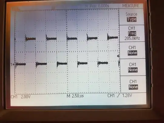
However in fact it appears to toggle at a frequency of only approximately 410kHz (which corresponds to a square wave of frequency 205kHz), as the below image shows:

Picture of the screen of an oscilloscope showing that the frequency at which the digital pin toggles is close to 410kHz

I used Timer0 but I get the same frequency with Timer1 and Timer2.

  • How can one explain that using this code I get this toggle frequency on the digital pin ?
  • How can I generate a custom binary signal over a digital pin at the highest possible frequency ?
Ramanewbie
  • 145
  • 3

1 Answers1

3

How can one explain that using this code I get this toggle frequency on the digital pin ?

Code takes time to execute. Your ISR, when compiled, looks like:

ISR(TIMER0_COMPA_vect)
{
 124:   1f 92           push    r1
 126:   0f 92           push    r0
 128:   0f b6           in  r0, 0x3f    ; 63
 12a:   0f 92           push    r0
 12c:   11 24           eor r1, r1
 12e:   8f 93           push    r24
 130:   9f 93           push    r25
    PORTB ^= 1 << 1;  // Toggle D9; this allows to measure the toggle frequency, however this could be replaced by some code to generate a custom binary signal
 132:   85 b1           in  r24, 0x05   ; 5
 134:   92 e0           ldi r25, 0x02   ; 2
 136:   89 27           eor r24, r25
 138:   85 b9           out 0x05, r24   ; 5
}
 13a:   9f 91           pop r25
 13c:   8f 91           pop r24
 13e:   0f 90           pop r0
 140:   0f be           out 0x3f, r0    ; 63
 142:   0f 90           pop r0
 144:   1f 90           pop r1
 146:   18 95           reti

That's 18 assembly instructions, each needing between 1 and 4 clock cycles to execute. Referencing the datasheet you can count the exact cycles needed and sum them up, yielding 31 clock cycles.

Toggling at maximum speed that would be 16MHz / 31 = 516kHz.

And then you have the rest of the code running between each call to the interrupt, so it's slower than that.

How can I generate a custom binary signal over a digital pin at the highest possible frequency ?

By not using interrupts, and writing a tight loop in assembly language.

Majenko
  • 105,851
  • 5
  • 82
  • 139