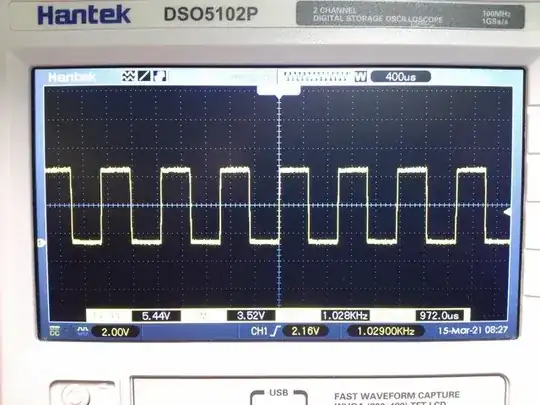
The PWM looks ok but I'm unsure of the analog signal.
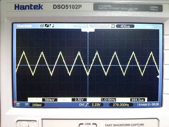
The “analog signal” looks like the PWM smoothed by a first-order
low-pass filter. It still has some oscillations, 584 mV
peak-to-peak. If you can tolerate that, then it's perfectly fine. If
not, then increase the time constant of your filter.
A first-order low-pass filter behaves, in its stop band, like an
integrator. Thus, a square signal is turned into a triangle. You are
seeing exactly the expected behavior.
The oscilloscope is set to defaults
There are no “default” settings in the oscilloscope. You probably used
the “autoset” button instead. This button tries to find some settings
that let you see something on the screen. I mean, some kind of signal,
not just straight line. If the signal is almost flat, the autoset will
increase the gain until you can see it is not flat. In this case, it
increased the gain by a factor 10 (200 mV / division instead of
2 V used previously). It also added a negative offset in order to
avoid the trace going out of the screen. See the small pentagon on the
far left with a “1” inside? On the first picture this tells you where
the zero (the reference potential) is relative to your signal. On the
second picture, the polygon pointing at the bottom of the chart tells
you the zero is off-scale.
If you want to really appreciate the smoothing action of the filter, you
have to look at its input (the PWM signal) and its output (the “analog”
signal) using the exact same settings. Connect the input, hit “autoset”,
and look. Then connect the output, do not change the settings (do not
hit “autoset”) and look at the output.
Better yet: forget the autoset button, adjust the settings manually and
mind their values.
Better yet: as you have a two channel scope, display both signals
simultaneously, using the exact same settings on both channels.