I'm using an Arduino Due that talks via SPI to an LCD (800x480) with the RA8875 controller chip. The most recent datasheet I could find is: RA8875 datasheet. Everything works as expected when using the Adafruit library. But, for my project, I want to maximize the communication speed between the LCD and the Arduino DUE.
Page 60 of the datasheet tells me that the maximum SPI speed to perform a SPIread is
system clock / 6.
Page 39 gives the formula for the system clock:
SYS_CLK = FIN * ( PLLDIVN [4:0] +1 ) / (( PLLDIVM+1 ) * ( 2^PLLDIVK [2:0] ))
There are some constraints:
From page 39:
FPLL = FIN * ( PLLDIVN [4:0] +1 ) must be equal to or greater than 110 MHzFrom page 91:
For an LCD of dim 800x480 2 layers 8bit color depth 60Hz framerate the pixel clock should be between 30 and 33MHz. (Registers are set to have 2 layers and 8 bit color depth).
A crystal of 20Mhz is soldered on the LCD ( FIN = 20 Mhz)
I have set the registers as follows:
| Register | Value |
|---|---|
| PLLC1[88h] | 24 |
| PLLC1[89h] | 1 |
| PCSR[04h] | 3 |
So, I expect:
- SYS_CLK = 20 Mhz * ( 24 +1 ) / (( 0+1 ) * ( 2^1 )) = 250 Mhz
- Pixel clock = SYS_CLK / ( 2^3 ) = 31.25 Mhz
- Max. spi speed = 250 Mhz / 6 = 41.66 Mhz.
I think to obey every given constraint. But when I use an spi-speed of 30 Mhz, which is below 41.66 Mhz, I get a black screen.
I've put the Arduino sketch and the modified Adafruit library (Sven_RA8875) on google drive: Arduino sketch + modified library.
The same data but on a pastebin:
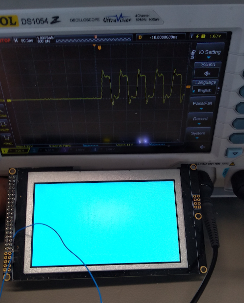
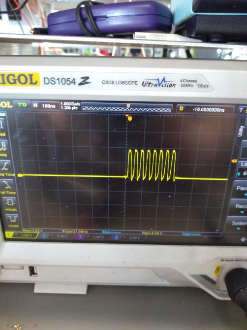
Edit by PPK: I add the pictures from paste pics to this post after I scaled and croped them.