I want to detect the exact time signal from an FM radio station. The signal is transmitted in the form of 5 short pulses and one long one. My task is to determine the presence of a pulse in the audio data stream and its duration. It is understood that the signal is received by the radio receiver and then the audio signal is fed to the atmega microcontroller. The pulse duration varies in the range of 100 ... 560 ms
How can you control the appearance of these pulses using a microcontroller, and also determine their duration? Below is an example of computer processing. The same is required to be implemented on a microcontroller.
I have a reference recorded signal in WAV format. This recorded signal from the output of the radio receiver contains both the speaker's speech, music, and the exact time signal:
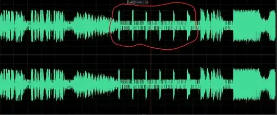
I know the time signal is centered at 1 kHz, so apply filtering to this signal. The filter has the following frequency response:
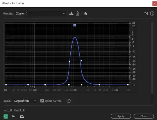


The signal after the filter looks like:

- It remains to apply the threshold device and duration selection. However, I do all this in an audio editor to understand the ongoing processes. In fact, I need to implement this on an arduino, so I really hope for your tips, because I don't know how to implement a filter on an arduino for one frequency, and I also don't know how to make a pulse detector and a meter for its parameters.
Below is the result of homodyne, the method suggested in the comments. On the test signal, the algorithm was able to identify the required pulses! It remains to write a sketch where there is a detection threshold and definition of the duration!
I was able to write a condition, when the threshold is exceeded, the LED turns on, and turns off otherwise. But I don't know how to make the definition of duration yet ...
Added after a few days:
I was able to assemble the entire structure, the sketch below does the following:
Listens to the audio signal coming to the analog input of the arduino from the radio receiver on the RDA5807M microcircuit, through an amplifier on one transistor, which provides signal amplification and offset to the positive range.
Performs homodyne processing: selects only the signal with a frequency of 1 kHz, all other frequencies are suppressed
Selects the optimal detection threshold for finding the exact time signal of 1 kHz frequency at the background level.
Calculates the duration of each pulse
Finds the exact time by the last impulse using the recalculation formula.
Thus, at the moment I get the exact time digit in the serial port monitor.
But the end result I want to get is setting the resulting digit on a seven-segment display. Having looked at the sketches of his work, I found that the values in the loop are constantly processed there, which again slows down the microcontroller, but for me this is unacceptable. As I understand it, you need to write a separate function into which you pass the value of the hour and set this value on the indicator only once an hour. But I don’t know how to implement it. I ask for help!
/ * Last edited on January 25, 2021.
1 kHz homodyne signal detection
This program continuously samples analog input A0 and uses a homodyne
detection circuitry for signal identification at 1 kHz (+/- 24 Hz at -3 dB).
The A / D converter is set to "free running mode" and takes one sample every 104 µs.
The samples are multiplied by two generated 1 kHz signals ("local oscillator") in quadrature to each other.
The products are then low-pass filtered with a time constant of 64 sampling periods (6.656 ms),
which gives (I, Q) signals with a bandwidth of 24 Hz.
Finally, the signal strength is calculated as I ^ 2 + Q ^ 2.
The program is designed for Arduino Uno and will probably work on any AVR based Arduino,
having an ADC and operating at a frequency of 16 MHz.
For a detailed explanation, see
http://arduino.stackexchange.com/a/21175
Posted by: 2016 Edgar Bonet Orozco.
- /
// Here is everything related to the parameters of the RDA5807M receiver:
#include <Wire.h>
#define RDA5807M_RANDOM_ACCESS_ADDRESS 0x11
// registers
#define RDA5807M_REG_CONFIG 0x02
#define RDA5807M_REG_TUNING 0x03
#define RDA5807M_REG_VOLUME 0x05
#define RDA5807M_REG_RSSI 0x0B
// flags
#define RDA5807M_FLG_DHIZ 0x8000
#define RDA5807M_FLG_DMUTE 0x4000
#define RDA5807M_FLG_BASS 0x1000
#define RDA5807M_FLG_ENABLE word (0x0001)
#define RDA5807M_FLG_TUNE word (0x0010)
// masks
#define RDA5807M_CHAN_MASK 0xFFC0
#define RDA5807M_CHAN_SHIFT 6
#define RDA5807M_VOLUME_MASK word (0x000F)
#define RDA5807M_VOLUME_SHIFT 0
#define RDA5807M_RSSI_MASK 0xFE00
#define RDA5807M_RSSI_SHIFT 9
uint8_t volume = 7; // 0..15
uint16_t freq = 938; // 107.3FM
uint16_t reg02h, reg03h, reg05h, reg0Bh;
// Receiver end
unsigned long startTime; // Turn on two timers, this
unsigned long elapsedTime; // and this one
int threshold = 300; // Set the maximum noise level
boolean timing = false; // I do not know...
#include <util / atomic.h>
// The analog input used must be between A0 and A5.
const uint8_t analog_in = 0;
// The frequency we want to define, in Hz.
const float SIGNAL_FREQ = 1000.0;
// Time bits.
const float SAMPLING_FREQ = F_CPU / (128 * 13.0); // 9.615 kHz
const long PHASE_INC = round (SIGNAL_FREQ / SAMPLING_FREQ * (1L << 16));
const int LOG_TAU = 6; // tau = 64 / SAMPLING_FREQ = 6.656 ms
// Set the ADC to constant conversion mode "free running mode"
static void configure_adc ()
{
ADMUX = _BV (REFS0) // ref = AVCC
| _BV (ADLAR) // left adjust result
| analog_in; // input channel
ADCSRB = 0; // free running mode
ADCSRA = _BV (ADEN) // enable
| _BV (ADSC) // start conversion
| _BV (ADATE) // auto trigger enable
| _BV (ADIF) // clear interrupt flag
| _BV (ADIE) // interrupt enable
| 7; // prescaler = 128
}
// Demodulated (I, Q) amplitudes.
volatile int16_t signal_I, signal_Q;
// Interrupt handler is called every time the ADC is ready to read.
ISR (ADC_vect)
{
// Read the ADC and convert to a signed number.
int8_t sample = ADCH - 128;
// Update the phase of the local oscillator.
static uint16_t phase;
phase + = PHASE_INC;
// Multiply samples by square waves in quadrature.
int8_t x = sample;
if (((phase >> 8) + 0x00) & 0x80) x = -1 - x;
int8_t y = sample;
if (((phase >> 8) + 0x40) & 0x80) y = -1 - y;
// First order low pass filter.
signal_I + = x - (signal_I >> LOG_TAU);
signal_Q + = y - (signal_Q >> LOG_TAU);
}
/ * Return the power reading. * /
static uint16_t get_power_reading ()
{
int16_t I, Q;
ATOMIC_BLOCK (ATOMIC_RESTORESTATE) {
I = signal_I;
Q = signal_Q;
}
return sq ((int8_t) (I >> LOG_TAU)) + sq ((int8_t) (Q >> LOG_TAU));
}
// *********************************************** ***********************
void setup ()
{
configure_adc ();
Serial.begin (9600);
// Receiver start:
Serial.begin (9600);
Wire.begin ();
// Register 02h - enable, settings
reg02h = RDA5807M_FLG_ENABLE | RDA5807M_FLG_DHIZ | RDA5807M_FLG_DMUTE;
setRegister (RDA5807M_REG_CONFIG, reg02h);
// And then we decided to further strengthen the bass: (I don't need this, I need to somehow remove it)
reg02h | = RDA5807M_FLG_BASS;
setRegister (RDA5807M_REG_CONFIG, reg02h);
// Register 03h - select radio station
// After reset in register 03h, the default value is 0
// Thus BAND = 00 (87..108MHz), STEP = 00 (100kHz). Let's leave them as they are
reg03h = (freq - 870) << RDA5807M_CHAN_SHIFT; // chan = (freq - band) / space
setRegister (RDA5807M_REG_TUNING, reg03h | RDA5807M_FLG_TUNE);
// Register 05h. Set the volume, do not change the rest of the beats
reg05h = getRegister (RDA5807M_REG_VOLUME); // Read the current value
reg05h & = ~ RDA5807M_VOLUME_MASK; // Reset the VOLUME bits
reg05h | = volume << RDA5807M_VOLUME_SHIFT; // Set a new volume
setRegister (RDA5807M_REG_VOLUME, reg05h);
// Receiver end:
}
void loop ()
{
// Print power readings every 8ms.
static const uint16_t print_period = 8;
static uint16_t last_print;
uint16_t now = millis ();
if (now - last_print> = print_period) {
//Serial.println (get_power_reading ()); // Build a graph by which you can determine the optimal threshold
// If the signal has exceeded the threshold, start timing:
if (get_power_reading ()> threshold &&! timing)
{
startTime = millis ();
timing = true;
}
// If the signal is below the threshold, stop the countdown and display the amount of time passed - the pulse duration:
if (get_power_reading () <= threshold && timing)
{
elapsedTime = millis () - startTime;
timing = false;
//Serial.println(elapsedTime);
if (elapsedTime> = 80 && elapsedTime <= 580)
{
int h = floor ((elapsedTime - 100) / 20); // Get the time in hours, but there are 6 pulses, but only the last one is needed.
//Serial.println(h);
// "valround" --- Round to the nearest integer,
// "floor (x)" --- Round down to integer
if (h> = 1 && h <= 24) // If the time is defined as abnormal, beyond reasonable limits, then simply forget it:
{
Serial.println ("Exact time:");
Serial.print (h);
Serial.println (": 00");
}
}
}
last_print + = print_period;
}
}
// Receiver start:
void setRegister (uint8_t reg, const uint16_t value) {
Wire.beginTransmission (0x11);
Wire.write (reg);
Wire.write (highByte (value));
Wire.write (lowByte (value));
Wire.endTransmission (true);
}
uint16_t getRegister (uint8_t reg) {
uint16_t result;
Wire.beginTransmission (RDA5807M_RANDOM_ACCESS_ADDRESS);
Wire.write (reg);
Wire.endTransmission (false);
Wire.requestFrom (0x11, 2, true);
result = (uint16_t) Wire.read () << 8;
result | = Wire.read ();
return result;
}
// receiver end