I am trying to setup L298N motor driver controller with my Arduino. Different online schematics about how to connect them are mostly similar - but they differ in powering the Arduino from the drive controller's 5v pin.
I am connecting 7.5v to the Vin and Gnd to the motor driver controller screw terminal , and I wish the power the Arduino from the 5v screw terminal. Since I am planning to use the 5v screw terminal as output I am choosing to leave the 5v jumper on.
Here are 3 of the schematics I've found online,
- Source Homemade-circuits:


This is what I was expecting to see. But from Arduino Uno Rev3 Faq,
Vin -- The input voltage to the Arduino board when it's using an external power source (as opposed to 5
volts from the USB connection or other regulated power source). You can supply voltage through this pin,
or, if supplying voltage via the power jack, access it through this pin.
5V -- This pin outputs a regulated 5V from the regulator on the board. The board can be supplied with power
either from the DC power jack (7 - 12V), the USB connector (5V), or the VIN pin of the board (7-12V).
Supplying voltage via the 5V or 3.3V pins bypasses the regulator, and can damage your board. We don't advise it.
This one looks wrong to me. I am under the assumption that Vin pin is expecting 7-12V because it's connected to voltage regulator which will cause a 2v drop. Which mean I should not connect 5v from the motor controller to Vin - making this schematic incorrect. Is my analysis correct? Here is an answer that says I can not use the 5v pin to power an Arduino since it an input pin and not an output pin.
- Source teachmemicro:


This one looks ok to me since the 5v source at motor controller is a regulated source and that's what exactly Arduino is expecting on 5v pin based on aforementioned FAQ. Can I implement is safely?
- Source Instructables:
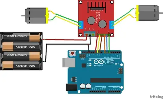

I do not know if it's correct or not. Notice that the 5v screw terminal is not connected to Arduino in any way. Is it setup going to work? I am wondering where the Arduino is getting its power from?
I am wondering which schematic should I follow. I am hesitant to hook up my L298N motor driver and Arduino without without understanding why each schematic is choosing to power the Arduino differently.