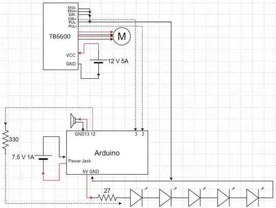
The last couple months I’ve been working on this project, I’m nearing its end and I’m getting really excited! However, this is still pretty new to me and so I was hoping my electrical diagram/accumulated knowledge could be verified before I go and start spending money on parts. All criticism is welcome as are any additional resources. Thank you in advance!
Logic:
Arduino setup:
Arduino pins (aside from the power section) at the bottom are capable of outputting up to 40mA at most and when using multiple pins, no more than 200 mA should ever be drawn at once
Piezo buzzers are the only electrical component that do not need resistors
This was taken directly from How To Mechatronics, attaching a 330 Ohm resistor to the LED strip lowers its electrical noise
The other resistor attached to the LED strip should be 25 ohms, seeing as I don’t have one though I will be using a 27-ohm resistor instead. Where 5 LED’s on the strip should take up 300mA (each GRB uses 20mA and I’m using 5 in total, therefore 20 x 3 x 5 = 300). Using Ohms law R = V/I, therefore R = 7.5/0.3, therefore R = 25.
**I would like to add that I also looked at Watt’s law and was a big confused as I got a current of 200 mA instead (as the LED’s each use between 0.1 – 0.3 Watts, therefore I = W/V, therefore I = 1.5/7.5, therefore I = 0.2) I went with the 27 ohms instead of the 37.5 ohms watts law gave me instead because How To Mechatronics really seemed to know what was up I chose to power the board via the 7.5V, 1A adapter mostly because I wanted its voltage-in to be regulated and seeing as it won’t be plugged into a computer, I thought USB was a bit sketch and it made more sense to use the power port as opposed to the Vin pin.
Motor setup:
The motor was chosen based off of my need for high torque – the door handle I am trying to push requires 5 pounds (raised to 6 pounds for extra breathing room) and the entire handle is 4.5 inches (lowered to 3 inches for breathing room) in length (the measurements were provided by a friend as I wont be home for a little bit, might seem a bit overkill but its just cause I don’t think they are entirely accurate in the first place). Using these measurements and the equation Torque = length x Force I got the required torque had to be greater than 0.3572kg/cm to open my door. Knowing this I took a look at a bunch of Nema stepper motors and chose one capable of producing that torque (based off of its holding torque) that was the lightest and smallest. I wanted something light as I am still unsure how I will be mounting this to my door…
Originally, I was going to use the L298N but seeing as how using the 5V pin off the Arduino is not recommended for powering it and that they generally don’t dissipate heat that well for their motors I decided not to
Lastly, the 12V 4A power supply was chosen because I needed something stronger than 9V and I wanted to save money. Seeing as I would have the 0.5A - 0.7A current option selected (to my knowledge anything more could cause damage unlike with the Arduino, extra current is not necessarily a bad thing in this case) it’s a bit overkill. I’m thinking it shouldn’t cause any thermal limiting though seeing as it is rated to 4A and its not as if my motor will be going that often anyways :)
Links (all links except for the motor which goes to pololu redirect to amazon): 7.5V 1A Power supply: https://www.amazon.ca/Belker-Adjustable-Universal-Household-Electronics/dp/B07NKZCWT1/ref=cm_cr_arp_d_product_top?ie=UTF8 12V 4A power supply: https://www.amazon.ca/COOLM-Adapter-100-240V-Doorbell-5-5X2-5MM/dp/B07H2T31JJ/ref=sr_1_6?dchild=1&keywords=10V+4A+POWER+SUPPLY&qid=1606959202&s=hi&sr=1-6 KEYESTUDIO W5500 Ethernet Arduino (Uno): https://www.amazon.ca/gp/product/B079G4WDGW/ref=ppx_yo_dt_b_asin_title_o03_s00?ie=UTF8&th=1 NEMA 14 stepper motor (2.7V, 1 A/Phase): https://www.pololu.com/product/1209 TB6600 stepper motor driver: https://www.amazon.ca/TB6600-Stepper-Driver-Controller-tb6600/dp/B07B9ZQF5D/ref=asc_df_B07B9ZQF5D/?tag=googleshopc0c-20&linkCode=df0&hvadid=292963865944&hvpos=&hvnetw=g&hvrand=11283888445696292979&hvpone=&hvptwo=&hvqmt=&hvdev=c&hvdvcmdl=&hvlocint=&hvlocphy=9001232&hvtargid=pla-524548131497&psc=1 LED strip (WS2812B): https://www.amazon.ca/gp/product/B01CDTED80/ref=ppx_yo_dt_b_asin_title_o06_s00?ie=UTF8&psc=1
