5

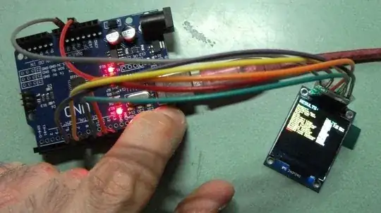
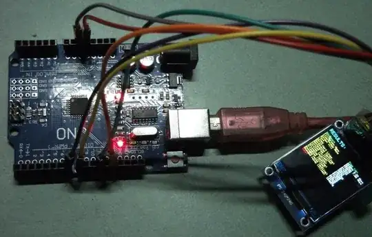
I am trying to get the ST7789 TFT display to work with Arduino. I followed online guides for connections and am using the fast library fron github and included workbench ino (https://github.com/cbm80amiga/Arduino_ST7789_Fast). Problem: The program runs and drives the display but the image is corrupt and only partial. I discovered that if I quickly and firmly press the reset button - and keep it pressed down - the image at the moment of reset press suddenly becomes full and good (albeit static because reset is pressed). Ofcourse as soon as I release the reset button the program restarts with the same corrupt image (the pictures below illustrate the issue).

This is the final screen of the demo showing the corrupt image This is what happens when I press and hold the reset button - the image suddenly becomes nice!

I could not find a description of this particular problem by online searching. Here is what I tried to fix it (all to no avail):

  • I confirmed all pins are correct as defined in the ino script.
  • I ensure only the 3.3v power line is used. I have never connected the Vcc to 5 v
  • I tried with a genuine Arduino UNO as well as a clone - both show the same behaviour.
  • I used 1k:2k resistor voltage dividers for the data lines, res and DC - these did not help. In fact the display did not work at all with the voltage dividers, only the backlight came on and the screen flickered slightly. I checked that I was getting ~3v in the middle of each divider.
  • I used two separate ST7789 display boards, bought from two separate sellers on different occasions - both show the same behaviour.

[Edits in response to comments below]

  • The same behviour occurs when using a sketch that uses the standard Adafruit libraries (as opposed to the fast library linked above).
  • The same corruption is seen when run on an arduino nano clone. However, with the nano, pressing the reset button shows only a fleeting glimpse of the full image prior to resetting (i.e. holding down the reset button does not preserve a static image on the screen).

Any ideas about what is going on and how to fix it? Thanks.
WildCat
  • 323
  • 3
  • 11

1 Answers1

3

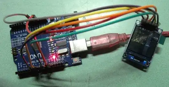
I found the answer to this problem. After reading multiple web pages / YouTube videos from multiple authors on this device and ~all of them warning you must never connect the Vcc to 5v or it will destroy the display, I found one or two that suggested you could use 5v because in this particular module there is a built-in regulator. So, faced with the thing being useless anyway, I decided to take the plunge and connect the Vcc of the TFT to the 5v pin of the Arduino and - hey presto - it works perfectly (see picture below: note the clear full image without the reset button being held down and also notice the voltage pin of the TFT is now connected to Arduino 5v compared to the pictures in my question). enter image description here

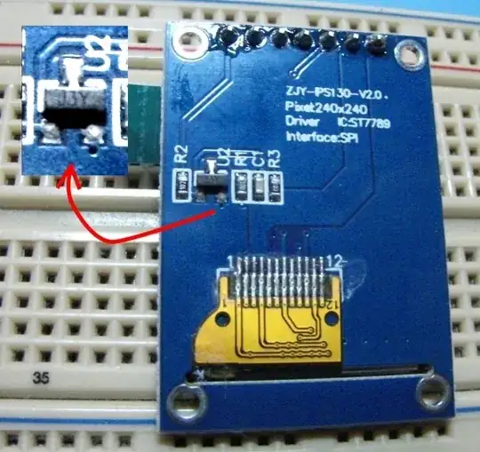
The picture below shows the back of my TFT display module and, from what I have read, it is the J3Y transistor that is key to the voltage regulation in this module. enter image description here

I hypothesise that pressing the reset button must have allowed equalisation of the voltages somehow but it is beyond my knowledge to explain it. I tried measuring the 3.3v pin on the Arduino with a voltmeter while holding down the reset button but I could see no change (the TFT module was not in situ for this test so maybe there is some interaction between Arduino and the TFT circuitry during reset).

Please note: I suspect this is a peculiarity of the particular TFT display module I have. Please DON'T run your 3.3v devices at 5v unless you have good reason to believe that they can take it. I only tried this after reading a couple of pages (including the detailed specs on the TFT module seller's listing) that suggested it would be OK with my particular TFT module - your's may be different. But if you have the same problem you see in my question then maybe that is something to consider. Thanks to those who have responded.

WildCat
  • 323
  • 3
  • 11