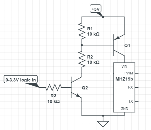
I've been trying to turn off an MHZ19B (datasheet and teardown photos: revspace.nl/MH-Z19B). I've used an Arduino, NPN, PNP transistors and mosfets as well as the diagram below for connecting the sensor to an ESP32. In all cases, PWM communication works great! I can power off the sensor, turn it back on, and values derived from PWM communication are as expected. However when I connect the Rx and Tx lines (to software serial Tx and Rx pins respectively on Uno pins A0 A1 or ESP32 pins 32 33) they spit out gibberish and the PWM signal also suffers hiccups.
Otherwise, without any kind of logic power control, the MHZ19B works great and can communicate with anything via UART, even my PC usb port via FTDI.
I added resistors to the Rx and Tx lines so the voltage on them doesn't exceed Vcc. I tried 1n4007 diodes (they're the only ones I have; no Schottky diodes either). I tried an NPN equivalent optocoupler. I also tried powering the sensor from my breadboard. I don't own an oscilloscope :(
My High School teacher said to just use PWM, but as I searched for a solution to this error, I noticed hundreds of others have this exact same problem with all sorts of different sensors and loads with ICs; no one has come up with a general solution.
I've been obsessing with this for weeks and if anyone can help or can recommend a book about sensor schematics I would really appreciate it. Thanks!