1

i have a small project where i just sucessfully destroyed my frist of 5 Digisparks (Attiny85). enter image description here

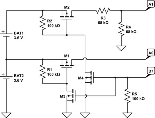
In the Picture you see the Cirucit. I have 2 Liion cells connected in series to get high enough voltage to step it down to constant 5V. To these 5V some Neopixels and a Digispark controller are connected which will set the color for the Neopixels. A0 and A1 measure the Voltage of the Cells to signal the user if the Voltage is to low so it can manually be switched of. While prototyping it i didnt have the 10k resistors in there.

Now what happend: While connecting the cells after each other the Controllers LEDs already lit up with the Frist cell. I guess it was powered trough the A0 pin (again i didnt have the 10k resistor in there), so i guess the internal IO Protection diodes conductet the voltage trough and this way the controller got damanged. Since this happend it wont turn on Anymore.

The problem: since i have really small space i cant use a multiple pole switch to also remove the voltage from the IO pins and therefore i will always have voltage von A0 and A1 while there is no 5V Supplyvoltage. I would guess that the Series resistance on the pin would be enough to Limit the current trough them and this way protect the controller from damange. But i dont really have experience with that and hope that you guys can give me some hints what could also be a problem or what could help :) I really dont want to destroy a second one xD

Thanks in advance and have a nice day :)

KidCe
  • 11
  • 1

3 Answers3

2

For this I would recommend isolating the power from the batteries with P-channel MOSFETs and only switching them on when you want to sample the voltage. This means that there is no power consumption at all (aside from an absolutely minuscule leakage current) when turned off.

The whole setup would require 4 MOSFETs - two P-channel and two N-channel. They don't need to be big, since the currents involved are very small, but they do need to have "logic level" thresholds, ideally < 1.5V (-1.5V for the P-channel).

The basic circuit looks like this:

schematic

simulate this circuit – Schematic created using CircuitLab

The circuit is made up of two identical segments - M1+M3 and M2+M4. The operation is fairly straightforward:

  • M1 (M2) is kept in the OFF state by R1 (R2) pulling the gate up to source.
  • M3 (M4) can pull the gate of M1 (M2) LOW turning it on and allowing current to flow
  • Any GPIO pin (D7 in this example) can control both M3 and M4 together
  • R5 keeps M3 (M4) off when there is no power - otherwise it floats.
  • R3/R4 are your existing voltage divider.

The purpose of M3 and M4 is to both turn the GPIO (D7) into "open drain" so that it's either pulling down or floating high (rather than driving high at 5V) and to isolate the two pullup gate voltages. The same effect could be achieved by two diodes and one MOSFET but it's simpler to just use two MOSFETs and not have to get diodes as well.

Majenko
  • 105,851
  • 5
  • 82
  • 139
0

As a general rule, you should not apply a higher voltage to the logic pins of digital ICs than you do to their power pin. This means that if you disconnect power, you must also shut off voltage to the logic pins.

Failure to follow that rule will often destroy an IC.

I don't know about the specifics of the inputs on your DigiSpark. 10K resistors will certainly lower the current that is able to flow into those pins, but you would still be breaking the "don't put more voltage into an input pin than you put into the VIN pin" rule.

Duncan C
  • 5,752
  • 3
  • 19
  • 30
0

If all you are doing with A0/A1 is 'signalling the user that the voltage is too low for continued operation', then consider the following:

  • remove the lead from the top of the lower battery entirely
  • instead of the 1/1 voltage divider, use something like 10/1 (i.e. a 680K on top and a 68K on the bottom to provide a large series resistance (making the steady-state current drain on the battery negligible). This will also put the nominal full-charge voltage as measured at the ADC input well within the DC voltage range of the Digispark at a small cost in accuracy. The specs for the ATiny85 ADC input impedance is something like 100 MegOhms, so the accuracy drop from using a 680K series resistor shouldn't be more than a few percent. Use a variable power supply to calibrate the A/D setup so your controller will alert the user when the battery stack gets low. If you don't have a variable power supply, consider something like this

Frank

starship15
  • 782
  • 4
  • 12