I am new to Arduino which I got only this week for my project which sends sms from my windows application.
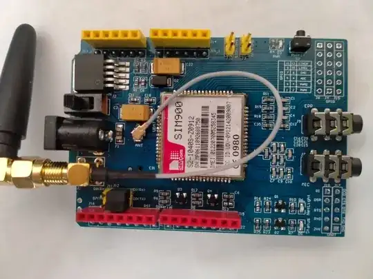
I have Arduino Uno R3 and GPRS Shield (Simcom) Sim900 (S2-1040S-Z0912)
I am currently following this guide > https://educ8s.tv/arduino-gsm-shield/
As of the moment I have problem connecting the Sim900 to Arduino (I think Arduino cannot detect Sim900). The Arduino is working properly as my PC detected it. Also I confirm that the SIM900 is working properly as I can call the Sim inside and it is ringing (also the led on the device is blinking almost every 3 secs or so)
I found this, but I'm planning to use USB powered only as I only need the SMS feature so I am stacking the SIM900 on top of the Arduino. How to communicate the Arduino board with SIM900?
I am using this library http://www.tinyosshop.com/datasheet/GSM_GPRS_GPS_Shield_GSMSHIELD.rar
and below is the sketch:
#include "SIM900.h"
#include <SoftwareSerial.h>
#include "sms.h"
SMSGSM sms;
int numdata;
boolean started=false;
char smsbuffer[160];
char n[20];
char sms_position;
char phone_number[20];
char sms_text[100];
int i;
void setup()
{
Serial.begin(9600);
if (gsm.begin(9600))
{
Serial.println("\nstatus=READY");
started=true;
}
else
Serial.println("\nstatus=IDLE");
if(started)
{
if (sms.SendSMS("214", "?15001"))
{
Serial.println("\nSMS sent OK.");
}
else
{
Serial.println("\nError sending SMS.");
}
}
};
void loop()
{
if(started)
{
sms_position=sms.IsSMSPresent(SMS_UNREAD);
if (sms_position)
{
Serial.print("SMS postion:");
Serial.println(sms_position,DEC);
sms.GetSMS(sms_position, phone_number, sms_text, 100);
Serial.println(phone_number);
Serial.println(sms_text);
}
delay(2000);
}
};
and here is the output
Trying to force the baud-rate to 9600
1200
2400
4800
9600
19200
38400
57600
115200
ERROR: SIM900 doesn't answer. Check power and serial pins in GSM.cpp
status=IDLE
What I have tried so far:
I tried the sketch with SoftwareSerial mySerial(7, 8); and SoftwareSerial mySerial(9, 10) which i found on other tutorials but didn't work.
I tried modifying GSM.cpp and modify the value of _GSM_TXPIN_ and _GSM_RXPIN_ to 7, 8 and 9, 10 but didn't work.
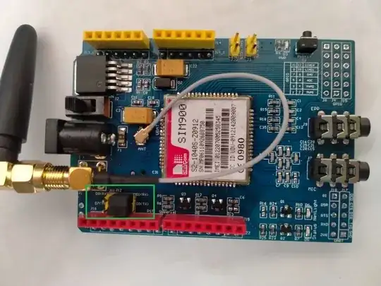
Found that the pin on my Arduino is RX=0 and TX=1, and SIM900 is TX=0 and RX=1, tried the SoftwareSerial code above but with 0, 1 and GSM.cpp with 0, 1 but still not working.
I am currently still trying every other sketch i find on the internet but nothing works.
EDIT: This is the link for the module i bought https://www.lazada.com.ph/products/sim900-gsm-shield-i267689740-s379728457.html?mp=1
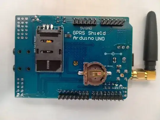
I cant find the link for the datasheet of this specific module so I will try to include the picture of the module


