I have previously asked this question:
Custom build of arduino on a pcb
And thanks to the answer by Majenco I have learned that my circuit works a lot better when adding a capacitor. For example I am using the NRF24L01 and it is much more stable when using a capacitor. I am placing the capacitor for now next to the power supply like this:
Right now I am running this on a breadboard. The Atmega328 chip is very cheap compared to the arduino uno board; therefore, I will like to continue building my projects based on the atmega328P-PU chip.
Anyways before printing the PCB based on the Atmega328P-PU chip, where should I place the capacitors in order to reduce the most noise? The capacitors are very cheap and making one good design will enable me for all my future designs to be based from this one.
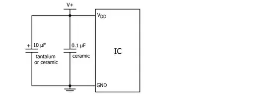
From researching on the internet I see a lot of different examples. Everyone uses different capacitance sizes. For example I have found this:
 I got that from this link: https://www.autodesk.com/products/eagle/blog/what-are-decoupling-capacitors/
On other places they say to place the capacitance closest to the pins such as from this video. If that is true should I just place one capacitor on pins 7 and 8. Lastly the other capacitor on pins 20 and 22?
I do not mind soldering extra pins knowing my circuit will have the best performance.
