3

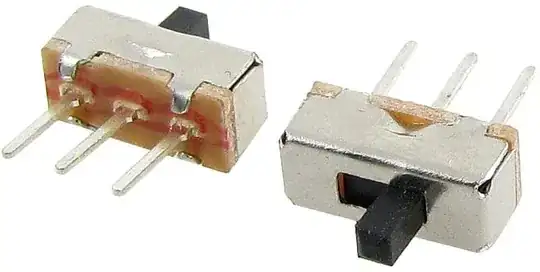
I purchased these slide switches recently because I want to use them in my project:

enter image description here

But I don't know what to connect up the three pins to and I can't find any information about them online. Nor can I find sample code. Can someone show me how to wire them up and provide sample code please? I just want to be able to check their state and save it as a boolean variable.

Saqib Ali
  • 93
  • 1
  • 2
  • 10

3 Answers3

5

As others have said, this is a SPDT (Single Pole Double Throw) switch. The center pin is common. When the switch is slid one way, it connects the center pin to the outer pin on that side. When you slide the switch the other way, it connects the center pin to the opposite outer pin.

See the link about SPDT switches Edgar provided in his comment: http://www.learningaboutelectronics.com/Articles/What-is-a-single-pole-double-throw-switch-SPDT

That explains these switches pretty clearly.

Connect the center pin of the switch to a digital pin on your Arduino. Connect one of the outer pins to ground.

Set the digital pin on the Arduino to INPUT_PULLUP mode.

Then, when you read the digital state of the pin, if it is LOW, the switch is closed. (Slid to the side of the pin you attached to ground.)

Duncan C
  • 5,752
  • 3
  • 19
  • 30
3

Since it has two possible positions, and three pins, you have a connection between pin 1 and 2 when position 1 is selected, and between pin 1 and 3 when position 2 is selected. As BSF comment below, the middle pin is common. This means it will be connected to the outside pins depending on where the switch is moved towards.

However, you always can verify this, in the following way:

To find out which is pin 1, pin 2 and pin 3, use a multimeter. Set it to continuity mode, or if you don't have that mode, to resistance mode, and put the red/black probes to two random pins. Check if the resistance is 0, in that case you know those two pins will be connected when position 1 is selected. If there is resistance, try other pins with the probes, until you know which are connected.

Than switch the position, and do it again.

Instead of a multimeter you also can 'hardwire' it to e.g. 5V -> pin 1, pin 2 -> resistor of 220 ohm -> LED -> GND And change pin 1 and pin 2 until you found which pins connect for which positions.

To use it for you Arduino, check for a normal simple switch example, but these are two in one, one for each position.
Michel Keijzers
  • 13,014
  • 7
  • 41
  • 58
1

These switches are actually a lot more simple than you would think. You have two positions, but you really only care about one of them, since if it's not in that position it must be in the other.

The central pin is the common, and when slid to one side it connects that central pin to the corresponding outside pin.

So you just use the central pin and one of the outside pins as if it were any other on-off switch or pushbutton. Treat it exactly the same (pullup resistor, which may be internal to the AVR chip, and connect the IO pin to ground through the switch).

If it's "on" (reads LOW) then the switch is in one position. If it's "off" (reads HIGH) then it's in the other position.

The only times you'd want to use both outer pins is if you were wanting to direct a signal to one of two different places, or select between two different incoming signals, or if the switch were a "3 position on-off-on" switch where it can be in either outer position or neither position (centre off), in which case you treat it as two separate switches, but with a common central pin that connects both to ground.

Majenko
  • 105,851
  • 5
  • 82
  • 139