4

I am making a device that measures temperature and vibrations and records the values onto an SD card. It will be a standalone device.

The hardware used: - Arduino Uno - PCF8523 RTC clock - MAX3186 + PT100 RTD temperature sensor - Adafruit data logger shield - Typical bare piezo sensor

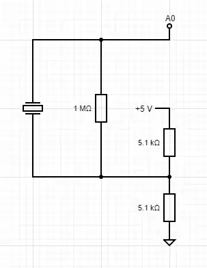
For the vibrations, a piezo sensor is used. Because it can produce a signal in two directions, I decided to use a voltage divider to offset the signal from GND. Two 5.1K resistors are connected from the piezo negative terminal to 5V and GND. A 1M resistor is placed in parallel with the piezo sensor. The positive terminal is connector to analog input 0.

Piezo circuit

The sensor is read 100 times per data point, the maximum and minimum values are stored and the final value is set to be the difference between the two (two times the amplitude).

USB
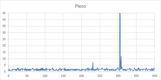
9V wall adapter

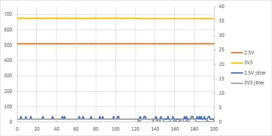
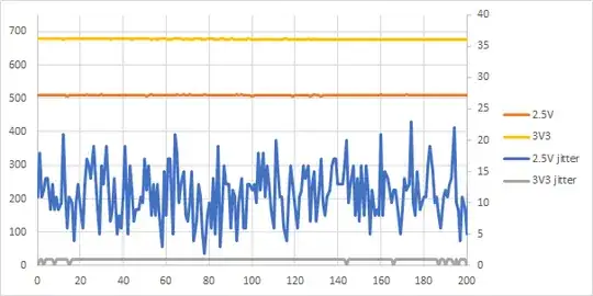
When the system is powered via a laptop USB port, the resting value has a jitter of a few bits. When a 9V wall adapter powers the arduino, the jitter is +/- 30 bits. Any small vibrations disappear in the noise.

USB with piezo

USB with piezo

9V with piezo

9V with piezo

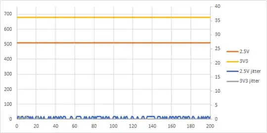
9V without piezo

9V without piezo

I would like some help to find the best way forward.

edit 29-10 17:53 Added better plots

edit 30-10 17:53 Added plots for 2.5V and 3.3V lines
2 Answers2

4

The 9V wall adapter is in most cases a switched power regulator with a high frequency. That's like a radio transmitter direct beside the wire. So there is nothing mystical, when the smooth USB Voltage does not show problems but the "radio transmitter" does.

There are two ways the power supply can impact: over radio wave or as ripples over the regulated Voltage of your Arduino.

I asked myself, which one it is (or even both)? If you use the extra regulated analog voltage reference (AREF) as the +5V on your Voltage divider, it would be more likely that the problem comes through the air. Then it would help if you activate the shield of the wire by connecting it to GND.

If a rippled supply voltage is the problem, you have to smooth it. Perhaps with a low pass filter (a big Elko between Vcc and GND).

Perhaps you have a solenoid iron core. Then you can wrap the wire to the piezo sensor a few times around it (near the A0 Pin). This technique is often used in computer power supplies to prevent the switching frequencies from escaping to the public power lines.

Peter Paul Kiefer
  • 1,893
  • 9
  • 11
1

In addition to what Peter Paul Kiefer suggests, you will also want to place an RC low-pass filter, between the piezo transducer, and the analog input.

You mention that you'll be sampling this value 100 times per second. So the cutoff frequency, for the filter, should be set to 50 Hz (the Nyquist frequency).