1

I'm reading the voltage with voltage divider:

schematic

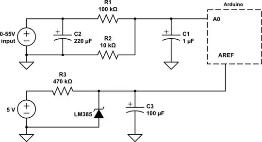
simulate this circuit – Schematic created using CircuitLab | Arduino is connected to both USB and a 9V adapter.

float r1 = 100000;
float r2 = 9980;
float adc, voltage, analog;
void setup() {
  Serial.begin(9600);
  analogReference(EXTERNAL);
  pinMode(A0, INPUT);
}

void loop() {
  for (int i = 0; i < 256; ++i) {
    analog += analogRead(A0);
  }
  analog = analog / 256;
  adc = analog * 1.228 / 1023;
  voltage = adc / (r2 / (r1 + r2));
  Serial.print(analogRead(A0));
  Serial.print(", ");
  Serial.print(analog);
  Serial.print(", ");
  Serial.print(adc);
  Serial.print(", ");
  Serial.print(voltage);
  Serial.println(" ");
  delay(100);
}

Here's the accuracy test result:

Input | Arduino | Difference
 1V      0.89V     -110mV
 2V      1.90V     -100mV
 3V      2.92V     -80mV
 4V      3.93V     -70mV
 5V      4.95V     -50mV
 6V      5.97V     -30mV
 7V      6.98V     -20mV
 8V      8.00      0
 9V      9.01      +10mV
 10V     10.02     +20mV
 11V     11.04     +40mV
 12V     12.06     +60mV

The input voltages measured by DMM and was spot on voltage, like 1.000V.

I didn't test voltages above 12V but it seems the difference is gonna increase by 20mV with each 1V increase, that means at 50V voltage reading is gonna be off by ~1V!

Even with 10bit resolution of Arduino I should have had steady accuracy with some percentage of difference(right?), but as you can see the result shows that the reading is not steady at all!

Why the voltage difference decrease/increase when voltage changes at the input?

ElectronSurf
  • 814
  • 4
  • 17
  • 43

2 Answers2

3

As stated by Majenko, the ADC can in principle have all sorts of errors. However, if you look at your data, you should notice that the error is essentially linear with the voltage. This means that the non-linearity error is quite small, and you are mainly seeing the offset and gain errors. This is fortunate, because these errors are easy to remove, given good calibration data.

The table you wrote in in your question happens to be a perfectly good calibration table. By fitting a straight line to it you can get a calibration function, and then correct the readings simply by adding this to your code:

voltage = 0.9848815 * voltage + 0.125354;

Or you could instead figure out the correction at the ADC level and replace

adc = analog * 1.228 / 1023;

by

adc = (analog + offset) / scale;

where offset and scale are computed from the calibration.


Edit: Here is how I extracted the calibration coefficients from the data.

First, I saved the data in a text file calibration.tsv and cleaned it up to remove the units and add a comment marker (#) in front of the column labels:

#Input | Arduino | Difference
 1      0.89     -110e-3
 2      1.90     -100e-3
...

Then I looked at the data with gnuplot. Since I want to know how to correct the readings, I plot the amount I have to add (minus column 3) v.s. the Arduino reading (column 2):

plot 'calibration.tsv' using 2:(-$3)

At this point it appears it's linear with what looks like mostly quantization noise. I model this as a line of equation a*x+b, and compare the line with the data:

a = -1e-2
b = 0.12
plot 'calibration.tsv' using 2:(-$3), a*x+b

The line is quite off the data, but it's a reasonable first approximation. Now I ask gnuplot to perform a least squares fit, then take another look:

fit a*x+b 'calibration.tsv' using 2:(-$3) via a, b
replot

Now the fit looks quite good. When it completed the fit, gnuplot displayed:

Final set of parameters            Asymptotic Standard Error
=======================            ==========================
a               = -0.0151185       +/- 0.0002953    (1.953%)
b               = 0.125354         +/- 0.002173     (1.734%)

so now I know I can correct the data with:

voltage += -0.0151185 * volatage + 0.125354;

which is equivalent to what I wrote above.

Edgar Bonet
  • 45,094
  • 4
  • 42
  • 81
2

Yes, you are right that the Arduino ADC is not accurate. If you read the datasheet (ATMega328P section 28.9, ADC Characteristics) you can see a lot of "error" and "non-linearity" characteristics.

These all add up to inaccuracies in your readings. For example the "Offset error" at your VREF could be as much as ±4.4mV, and the "Gain error" the same. Non-linearity can be as bad as 2mV, etc.

The Arduino ADC is not meant to be accurate. It's meant to be simple and cheap to implement. (It is a "Successive Approximation ADC" - approximation here is the keyword...) If you want a higher accuracy then there are more suitable ADC chips available that give that accuracy.

Majenko
  • 105,851
  • 5
  • 82
  • 139