You need a voltage divider with resistors that have large values.
...but with all values I have tried one resistor almost melts as soon as you connect to battery.
This suggests that you have been using values that are too low.
So lets go through the calculations to select good resistor values.
1/4 Watt resistors are common and easily available so I will base my calculations on that. These calculations will also be suitable for 1/2 Watt and 1 Watt resistors.
I am also going to add some margin above the 65V max that the solar panel can output (plus it makes the math easier)
Max Voltage = 100V
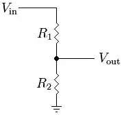
The voltage Divider:
Let's simplify. Almost all of the current will be going from your source, through the resistors (R1 & R2) to ground. Let's simplify by initially calculating the resistance required if R1 & R2 were combined into a single resistor:
From V = I x R
And P= V x I
Minimum resistor = V^2 / P
R = 75^2 / 0.25
R = 22500 Ω minimum
I would go further and say double that because I never like operating a resistor right on its maximum power rating. ie the minimum that R1 + R2 should equal is 50kΩ.
Lets play it safe and say that R1 + R2 is 100kΩ. The ESP8266 ADC pin input voltage range is 0 to 1V. Input is 0-100 V (which covers the required 40-65V range). Now all we have to do is calculate for R1.
Note: Most ESP8266 development boards come with an internal voltage divider. For these boards the input range is 0 to 3.3V.
Edit: The OP tells me that they get a max analog reading at 3.0V not 3.3V. Adjust the below calculations for an input voltage of 3.0V not 1V.
The formula to calculate the output voltage is:

Vout / Vin = R2 / (R1 + R2)
1 / 100 = R2 / 100kΩ
0.01 = R2 / 100k
Therefore R2 = 1k Ω
R1 = 100k - R2 = 99kΩ
I would up R1 to 100kOmega; as it will only result in a 1% error.
So R1 = 100kΩ and R2 = 1kΩ
Values of R1 = 49.5kΩ and R2 = 500Ω would also work.
In this case R1 could be made up of 2-3 resistors in series:
47KΩ
2.2KΩ
300Ω or 330Ω (optional)
The raw ADC input on the ESP8266 chip is 0-1V with a high input impedance (~20M). This means an op-amp buffer is not needed.
However, if you are interested, a op-amp circuit can be built from a 741 IC (among others) and is configured like this:


