1

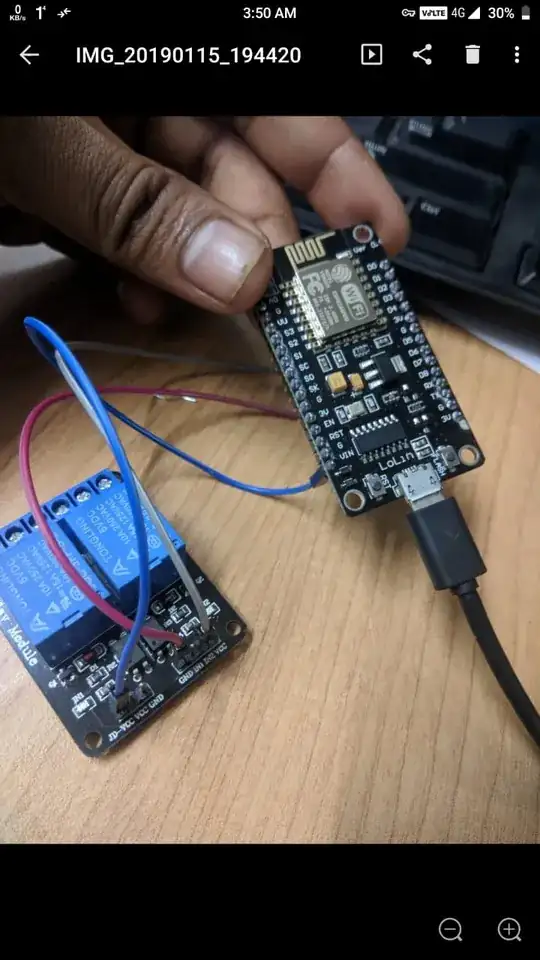
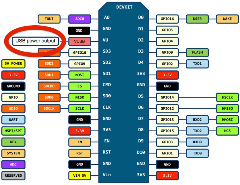
I have NodeMCU ESP8266N Lolin V3, my 5V relay is powered from Vin of the NodeMCU. The NodeMCU is powered from 5V USB.

My difficulty is when I measure voltage between Vin & GND, it is of 1.9V, but supposed to be around 5V as it is directly attached with usb 5V supply. Actually my relay is not working with the power tapped from Vin, but relay's led & NodeMCU led are blinking but relay coil does not trip. Please confirm is my NodeMCU having problems as voltage between vin & GND read 1.9V. https://drive.google.com/file/d/1Z6jYX4sCLmRxnWbtBYZCNW6LpckokaC9/view?usp=drivesdk enter image description here

Sumit Roy
  • 13
  • 1
  • 5

2 Answers2

3

The voltage on Vin when you power that board thru USB is not relevant ... Vin is not the pin you are looking for

You clearly have a Lolin NodeMCU (V3) board - the existence of Gnd and VU (looks like VV in your picture!!) between A0 and S3 pins indicates that

In documentaion easily found by searching for Lolin V3 pinout - VU is described a USB power output

Lolin v3 pinout

Use this pin to connect to JD-VCC on the relays

I've just now successfully done this with a 4 relay board

I would connect (nodemcu -> relay)

  • 3V3 to VCC
  • VU to JD-VCC
  • Gnd to Gnd
  • Dn to INm - i.e. choose a D pin on the NodeMCU and connect to an IN pin on the relay
Jaromanda X
  • 656
  • 1
  • 6
  • 12
0

It is hard to tell from your pictures but I don't think you have your relay connected properly.

Some problems i see:

  • Your esp8266n seems to be a 3 Volt device; it has 3V output pins
  • Vin usually feeds a regulator; the +V rail is usually after it
  • Your relay needs 5V but you only have 3V for power and signal

You will need a level shifter, and another powersupply to run your relay. You should be able to put 5v into Vin on your ESP and have it be powered, then you will need a level shifter to connect to the IN1 or IN2 of the realy so that you can control it with 3v. And the relay Vcc and GND also connected to the same power supply.

esoterik
  • 628
  • 3
  • 10