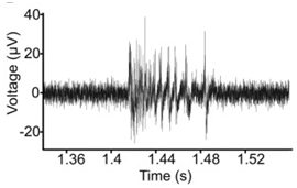
I have a signal that fluctuates between -70mV and 50mV. How would I get the arduino to read this.. Ultimately I am trying to graph the data in real time so it looks like this.
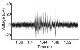
I have a signal that fluctuates between -70mV and 50mV. How would I get the arduino to read this.. Ultimately I am trying to graph the data in real time so it looks like this.
You need to amplify your signal and add 2.5V as a "virtual ground" for the amplification. This gets a little tricky, since you need a low-impedance VCC/2 source to feed the amplifier as a virtual ground. This would require a unity-gain buffer fed from a voltage divider:
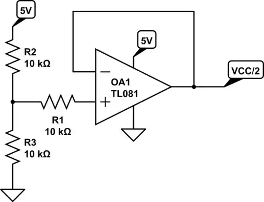
simulate this circuit – Schematic created using CircuitLab
Now you use that to feed the amplifier:
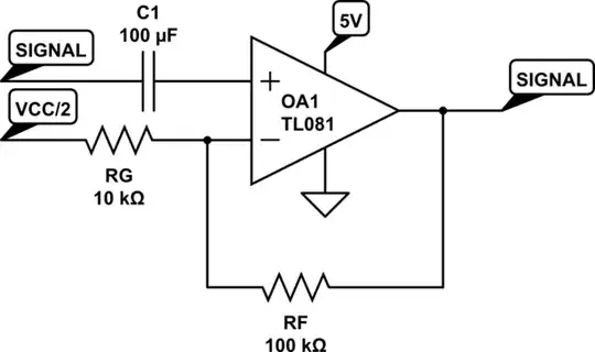
The gain is set by 1+(RF/RG), or 11 in this case, giving you -0.77V to +0.55V.
There is a simpler option, though. (There is another intermediate option but the editor lost it and I can't be bothered to spend the time recreating it).
This method does come at a cost, though: it inverts the signal. The -0.07 becomes 0.07 and the 0.05 becomes -0.05, and multiplied by the gain and added to the offset:
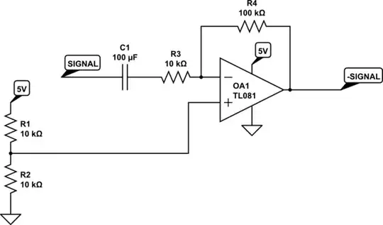
Here you get a transformation from -0.07V - +0.05V to +0.7V - -0.5V. That means that in software you then have to invert the value (simply subtract it from 0 after removing the DC offset).
You're basically shifting some of the complexity out of the circuitry and into the software.
Personally I use the inverting amplifier (the last circuit) because the virtual ground current is near zero, so you don't need a low impedance VCC/2 voltage source. It's also easier to create more sensible gains (like 10x) than the non-inverting amplifier, which always has 1 added to the gain.
Here is my try at this: if your voltage source doesn't mind sinking something like 150 µA, you could try something like this:
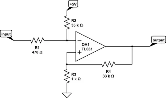
simulate this circuit – Schematic created using CircuitLab
This should map the input range [−70 mV, +50 mV] to [0.04 V, 4.06 V].