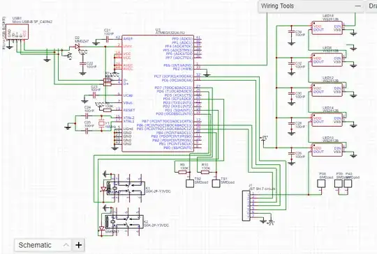
I made a custom ATmega32u4 board for my project. Components came from clone of Arduino Pro Micro (with bootloader and code which I uploaded) from AliExpress. I soldered everything in to my board according to my schematic but the board doesn't work. I don't have any signal from that.
Asked
Active
Viewed 729 times
1 Answers
5
You have an error in your schematic.
You have used the net name VCC for your main power circuit. However your USB incoming power is labelled as +5V.
That means you have two separate nets - +5V with power on it, and VCC isolated from it entirely.
You need to connect those two nets together - name them both VCC or both +5V so they form a single net (easiest is to adopt VCC since you use that on other connections too).
To "fix" your current PCB you could connect a small wire from the cathode of D2 to pin 44 AVCC on the main chip which will bridge the two nets together.
Majenko
- 105,851
- 5
- 82
- 139
