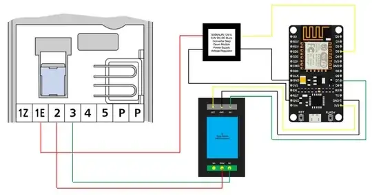
I'm doing some Home automation and am currently trying to automate my intercom system. My overall aim is to be able to detect when someone has pressed the buzzer and then to be able to open the door if I so wish. Below is the diagram of what I intend to do:
For reference, the buzzer board above is the is the Tegui 1378/1. The documentation can be found (in Spanish) here. I have been able to conclude the following so far about the pins:
1E: Buzzer
2: Common (12V dc)
3: Door lock
4: Microphone
5: Speaker
However, I have been unable to find any GND on this board. As a result, my diagram above makes use of the GND supplied on the NodeMCU instead; is this okay?
Whilst digging around, I found box in my main fuse box called a Tegui E-30. I believe that this takes in mains and drops it down to 12V for the intercom system. It has two pin outs simply labelled "9" & "10". Now, I am fairly sure that one of these is positive and the other negative; in which case, this would explain where the ground has been but I am unsure. It would be handy to know if it is the case that they are positive and negative respectively as it would be more convenient powering the NodeMCU from the 12V (after dropping it to 5V) rather than getting a massive USB cable from the other room.
I would really appreciate any more information people could give me. Both in terms of whether the above diagram would work but also whether someone can have more luck than me finding out exactly what the "9" & "10" pins on the E-30 are.
Thank you in advance for any help!
Kind regards, Rocco
