This is my first time posting on this forum. I have tried to format this question properly, but let me know if I need to correct anything. I searched to see if someone else had a similar problem, but let me know if someone has already answered this question.
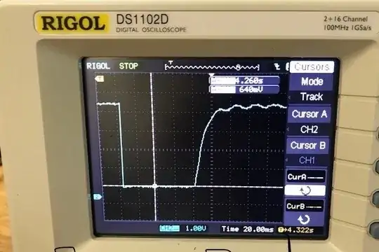
Overview: I am sending pulses to my Arduino, but sometimes one single pulse is interpreted as anywhere from 2 to 30 pulses. But after looking at the pulse on an oscilloscope (see Fig. 1) I am not sure why. When I use a really long wire the ratio of false pulses to legit pulses is about 1 to 1. I shortened the length of the wire and improved the situation, so that only 1 in about every 2,000 pulses is registered as a false pulse.
For one test, I added a capacitor to the short wire situation, but that increased the rise time and made the problem worse. I am currently using attachinterrupt and have tested the situation with using both a rising and falling edge. Right now, I mainly want to understand how interrupts work on the Arduino in light of my current problem, although I welcome general advice.
- When I set the interrupt to the falling edge, why does the Arduino still sometimes count 1 pulse as several? The falling edge in the photo, which is for the really long wire case, lasts about 40 microseconds and appears to have a clean break. The pulse remains low for about 80 milliseconds. Could the falling interrupt trigger during the rise time based off the oscillatory behavior shown in Fig. 1? I smoothed out the signal by adding in a 1 nF capacitor, but the Arduino still counted false pulses. So could the rise time period have anything to do with it? I also have a 10k Ohm pullup resistor connected to the Arduino's 5 V for the pulse path.
I have the relevant code attached below. I have much more code as well, but it deals with saving pulseCounts to the SD Card and uploading electricity consumption files through the cell network.
Cheers.
//Global Variables
unsigned long pulse_time = 0;
unsigned long last_pulse_time = 0;
byte code = 1; //code let's me see if a false pulse was reported for each
//SD file

void setup() {
  attachInterrupt(digitalPinToInterrupt(3), onPulse, RISING);
}

void onPulse() {
  pulse_time = millis();
  if ((pulse_time - last_pulse_time) > 50 ) {
    Serial.println("Good Pulse");
    pulseCount++;
    last_pulse_time = pulse_time;
  } else {
    Serial.println("Bad Pulse");
    pulseCount++;
    code = 2;
  }
}

