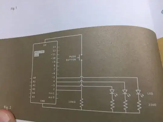
This is project 2 of their official arduino projects book called "Spaceship interface". I understand resistors normally reduce voltage so the LEDs don't burnout but here 5v is coming from either digital 3, 4, or 5 and it seems like it goes right into the LED before going through a resistor as it goes back to ground. This makes no sense to me.
4 Answers
It does not matter if a resistor is before or after a component, see the circuits below.
The resistor reduces the current, and this is true for the path where the resistor is in (until the interconnections before/after the resistor). In the examples there is only one path.

simulate this circuit – Schematic created using CircuitLab
- 13,014
- 7
- 41
- 58
It doesn't matter where the resistor is located (before and after are meaningless concepts). What is important is that the resistor is in series with the LED.
This produces an approximation to a constant current source (I = V/R). The actual current is lower due to the voltage drop across the LED, so is actually I = (V- VLED)/R. VLED varies; red LED is lower ~1.2V blue significantly higher.
The resistor serves 2 functions; to limit the current from the Arduino and to limit the current through the LED (either to limit brightness or protect the LED)
- 1,655
- 2
- 18
- 29
The resistor is to limit the current flow through the LED. A LED will burn itself out if given too much current and the maximum Arduino output current is 40 mA per leg (output). A quick calculation of V=I*R where V is 5 Volts, I = 40 mA leaves R = 5/.04 or 125 Ohms. You don't want to pull that much current from the Arduino so using 220 resistors is a safe bet at 22mA current draw per leg.
That 10K resistor keeps pin #2 at the ground potential until the button is pushed. Then the input to pin #2 is 5 Volts.
FWIW - that is an ugly drawing.
- 49
- 1
Most single or RGB LEDs can't take more than 20mA without risking overheating/burning up. Modern LEDs need as little as 5mA to be really bright. I use 1K resistors on boards where the LED is being used as an indicator (like Power, or Rx or Tx active, or for the L (SCK activity) LED. Sometimes 2.2K when 1K seems too bright still. Depends on the LED. Test first before soldering thinks up.
To calculate a resistor value for a desired current, use Ohms Law, V=IR, Voltage = current x resistance. Rearranged, Voltage/current = resistance.
If you know the Voltage, Vf, of the LED when it is on, and you are driving from an Arduino pin that outputs 5V, then: (5V - Vf)/current = resistor. With 5mA and say a Vf of 2.5V: (5V - 2.5)/.005A = 500 ohm.
You can determine Vf of an LED by using a 5V source and a 1K resistor. Connect the LED and resistor in series between 5V and Gnd. Measure the voltage across the LED, that is Vf. 5V - Vf = voltage across the resistor, Vr. 5V = Vf + Vr.
If you know the voltage across the resistor, Vr, you can calculate current flow: Vr/resistor ohms = current Amps. Say you measured Vr of 2.7V and used a 1K resistor. Then current = 2.7V/1000ohm = .0027A, or 2.7mA.
- 2,449
- 7
- 9
