1

I am using a Arduino Pro Micro from SparkFun (similar to Arduino Leonardo, cpu: Atmega 32u4). It has a analog input: A0, which I use to keep track of the battery voltage in my battery powered project (via analogRead).

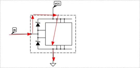
I found out that the red LED on the board lights up, even if there is no supply voltage on the usual inputs (micro-USB or Vcc). If I use a multimeter to measure the current between the battery and A0, I see that the analog input is drawing about 30mA if the Arduino is not powered.

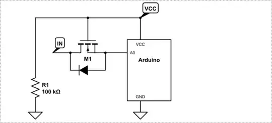
Is this the normal behaviour? Can I fix this via hardware?

Majenko
  • 105,851
  • 5
  • 82
  • 139
salami738
  • 13
  • 4

3 Answers3

3

Yes, it is normal behaviour, and it's called back-powering.

The current is flowing into the input pin and then flowing up through the ESD protection diode inside the chip to VCC. It's bad, because the ESD protection diode can't take much current and is easy to damage.

schematic

simulate this circuit – Schematic created using CircuitLab

You can prevent it from happening by adding some isolation into the input:

schematic

simulate this circuit

MOSFET M1 will be ON when VCC has power, but off when it doesn't. The 100kΩ resistor pulls the gate to ground when VCC is off so it doesn't float. The diode is the body diode of the MOSFET added for clarity. You don't need to add a diode there.

jsotola
  • 1,554
  • 2
  • 12
  • 20
Majenko
  • 105,851
  • 5
  • 82
  • 139
0

That's probably due to the clamping diodes. To protect the chip against ESD, there are diodes between the pins and Vcc and ground. This is to make sure that when charge builds up on a pin, it can flow to Vcc (when it's higher than the supply voltage) or to ground (when it's lower than ground level).

If you supply a voltage to a pin without a voltage on Vcc, current will flow through the pin to the supply line, powering the circuit.

You could probably solve this by adding a relatively large resistor in series with the pin.

tttapa
  • 1,330
  • 1
  • 8
  • 10
0

This is normal, if you abuse the chip in this fashion.

But you must take into consideration that it is strictly prohibited to apply a voltage to any I/O pin when the chip itself is unpowered.

This is because the protection diodes are not rated to supply power to the chip, and relying on them to do so may cause damage.

The literal statement of this rule is in the data sheet as

Voltage on any Pin except RESET with respect to Ground . . . . . . . . . .-0.5V to VCC+0.5V

If VCC is 0v, then the maximum voltage you may apply to any I/O is half a volt which is approximately (or just below) the point where a protection diode would begin to meaningfully divert current from the I/O to trying to lift the Vcc net of the chip, and likely the entire board.

Chris Stratton
  • 5,411
  • 20
  • 40