1

I have a OsiSense™ XMLP pressure sensor that I want to read from my Arduino uno. This is the circuit I am looking at building for measure 4 to 20 milliamp.
Reading 4 to 20 milliamps using Arduino

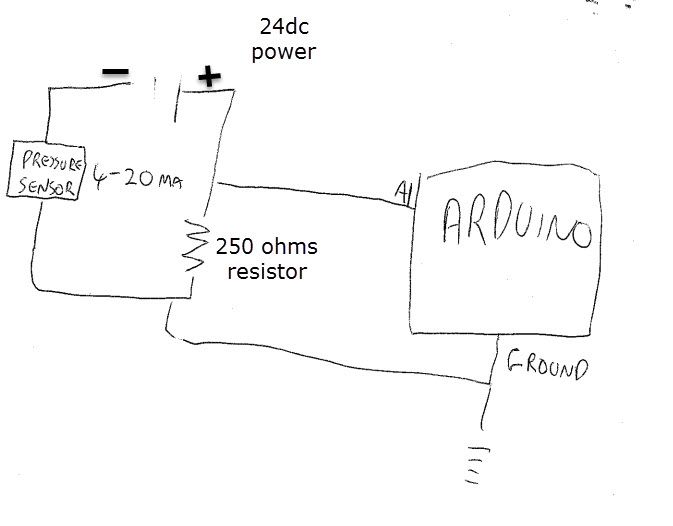
I've read online to find out how to build the circuit. Can you tell me if it is correct?

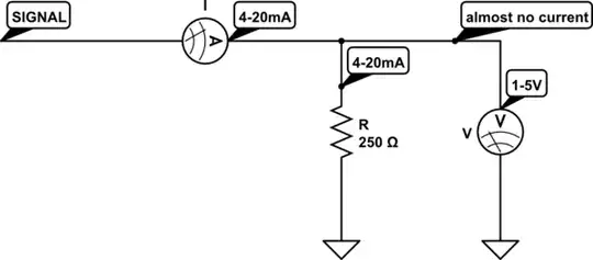
Also I dont understand why it works and I'm hoping you can correct my thinking. Following ohms law we want to leave 5v when 20 milliamps goes through the circuit. We know the voltage on the circuit is a constant 24 volts (short cable runs) and we know the maximum current is 20 milliamps so my maths says :

Resistance = Voltage / I (current)

We need to leave 5 volts for the Arduino to read when the sensor is at maximum pressure so we subtract 5 from 24.

Resistance = 19 / 20 milliamp

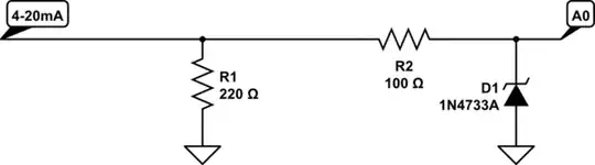
So the resistor to select to give us a maximum of 5 volts is a 0.95 Kilohms resistor. I dont see where the 250 ohm resistor comes in? please help.

resolver101
  • 155
  • 2
  • 2
  • 8

1 Answers1

4

To read a current with the Arduino you first have to convert that current to a voltage - and you do that by passing it through a resistance. The voltage dropped across that resistance as the current changes is what interests you.

schematic

simulate this circuit – Schematic created using CircuitLab

For a 4-20mA current you need to choose a resistance that gives voltages that are within the 5V range that an Arduino can read.

The biggest voltage drop across the resistor will occur when the current is at maximum (20mA) so you can use that to calculate a good resistor value to use:

R = V/I = 5 / 0.02 = 250

And for the same resistance at minimum current:

V=IR = 0.004 × 250 = 1

So across the resistor you would get between 1V (4mA) and 5V (20mA).

250Ω resistors aren't that common, so a more common value would be used instead - such as the commonly available 220Ω. Substituting the 250Ω for a 220Ω would give voltages:

@20mA: V=IR = 0.02 × 220 = 4.4V
@4mA:  V=IR = 0.004 × 220 = 0.88V

Both comfortably within the Arduino's range and also gives a bit of wriggle room in case of any small over-current conditions.

It can also be good to protect the analog input of the Arduino with a resistor + zener diode to prevent damage in the case that the resistor fails / becomes disconnected and you get the full output voltage applied direct to the Arduino:

schematic

simulate this circuit

Majenko
  • 105,851
  • 5
  • 82
  • 139