I want to detect when an LED is powered on using an Arduino NANO. The LED is part of an external circuit. The LED uses about 1.8V. Would the circuit below allow me to detect when the LED is switched on? Is this the correct method of doing it? (The LED in the diagram represents the external circuit).
3 Answers
I'm afraid your circuit does not work. In fact, the base of the transistor is always connected to the power, regardless the LED being ON or OFF. Therefore the BJT would be always in the ON-state. Also a current limiting resistor in series to the LED is missing (but I think that it was just for sake of simplicity).
Assuming that:
you can mount in series something to the LED
an additional 1.3-1.5V voltage drop will not cause too much issues (to be short: if the external circuit power supply is "large enough", and if you will not be too much upset if the LED luminosity will be smaller).
You want to sense a signal LED, i.e. let's say with a current smaller than 20 mA.
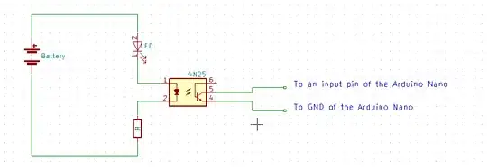
Then, the safest way would be to use an optocoupler, such as 4N25-4N35. Put the LED of the optocoupler (transmitter side) in series to the LED you want to "sense", and use the phototransistor side to sense the LED status: it's emitter goes to the GND to your Arduino Nano, the collector to any input, with pull-up (The pull-up is mandatory!).
In this way, when current flows across the LED, it will also flow in the optocoupler LED, therefore the optocoupler phototransistor will be ON.
Also, using the optocoupler the two systems are electrically insulated each other (and you won't need to share the grounds).
Below you can find an example.
EDIT:
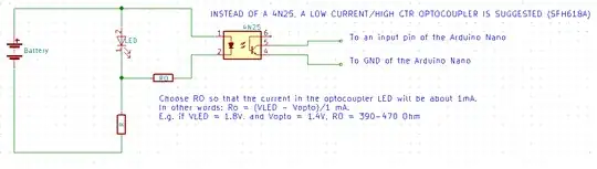
If you cannot wire the optocoupler LED in series (e.g. not enough voltage headroom because the power supply is too close to the LED Vf, or your LED is already on a PCB), you can connect the optocoupler in parallel.
Assuming the LED current is much larger than 1mA, you can use the following circuit. Choose RO so that the current flowing on the optocoupler will be 1mA (390-470 Ohm in your case). Usage of high current-transfer-ratio (CTR) optocoupler is suggested, but this might work also with a 4N25 or 4N35 (you'll be pretty close to the limit...)

- 411
- 3
- 10
The answer depends on your definition of "on".
An led is on if
There is voltage across I th or
There insufficient voltage across it, or
There is current through it, or
It generates light output, or
It generates sufficient light output.
...
Based on each of the above, there is an answer to your question.
- 2,813
- 11
- 13
No, you will not detect the LED state at all, as your transistor base is connected to the target circuit's supply rail, not a switched node.
Additionally, your circuit risks burning out the LED as it lacks a current limiting resistor.
Speaking more generally, the only safe way to do this with a fully unknown circuit is to have an optical sensor looking at the LED.
If you can determine that it is safe to make an electrical connection to the circuit (ie, that the internal ground is not riding on mains voltage) and that the point of the circuit you want to measure is within an allowed voltage above that, then you can connect the grounds and measure the switched side of the LED / resistor. But until you have far more electrical engineering experience, you are probably not in a position to make this safety determination. Even battery powered devices can generate dangerous voltages internally.
It's important that you not connect between the LED and resistor, but rather to whichever side of that series unit is not connected to a supply rail, as the voltage drop on the LED itself may not be sufficient to register.
Certain fancier LED drivers may give you problems, for example if they regulator current internally. Also, LEDs with PWM brightness control may require filtered polling, or even interrupts / hardware pulse-in.
- 5,411
- 20
- 40

