3

I'm learning the arduino platform and working on a circuit that connects the two pins of a piezo buzzer -- one to ground and the other to a digital pin of the arduino board. In this configuration, is the arduino's digital pin acting as the positive terminal of the circuit?

The arduino docs seem to suggest it is:

They (the digital pins) can provide a substantial amount of current to other >circuits. Atmega pins can source (provide positive current) or sink (provide >negative current) up to 40 mA (milliamps) of current to other devices/circuits.

Can the digital pins act as both positive and negative terminals in circuits? Does this question even make sense? What resources are out there that can help me better understand the underlying electronics of the arduino and microcontrollers in general?

Jog
  • 141
  • 1
  • 1
  • 4

6 Answers6

3

Step one: read the data sheet for the microcontroller. In there is a nice diagram that shows you exactly how the IO pins work.

The pins can work in 2 modes: input, and output. You're interested in output mode.

The drive state of a CMOS output pin consists of two MOSFETs, one connecting the pin to Vcc and the other connecting it to GND. Only one of the MOSFETs is ever turned on at a time, so the output pin is either connected to Vcc through one MOSFET, or connected to GND through the other.

When it's connected to Vcc it's said to be sourcing current, since it's at a positive potential compared to ground and current can flow out of the pin to light an LED (say), and when it's connected to GND it's said to be sinking current because current can flow into the pin to get to ground.

As an example of how it all works, consider how you would connect up and power a capacitative humidity sensor.

These sensors require a square wave at around 1KHz to operate. The humidity defines the impedance, and as part of an impedance divider (like a resistor divider) the output voltage is relative to the humidity.

Now, they don't just want any square wave, but require a square wave that reverses polarity around a virtual ground point, and that means reversing the polarity of the power across the sensor at 1KHz. How can you do that with an Arduino? The answer is simple:

Connect the sensor to two IO pins rather than 1 IO pin and GND.

Both pins are set as output, and one is set HIGH with the other set LOW. So the voltage across it is 5V.

Now you switch the outputs over, so the one that was HIGH is now LOW, and the one that was LOW is now HIGH. The power across the sensor has been reversed! It's now (effectively) -5V (compared to what it was before).

Majenko
  • 105,851
  • 5
  • 82
  • 139
3

The answer to your question is basically yes, you can use ATmega I/O pins as +/- power supply terminals for other circuits. But there's a limit to what you can power that way (20mA per pin and 100mA total per ATmega). In practice this means you can only power the simplest circuits (single LEDs per pin, and not many LEDs in total, for example). As a general rule, you should really look for other ways to power anything else.

Also, there's a problem with the citation you gave. That 40mA figure is the absolute maximum current per pin, but that should be avoided. Safest is to use about 20mA of maximum current per pin. Also, the ATmega pins should not have more than 200mA flowing through Vcc and GND (also an absolute maximum that should also be avoided).

Usually, you should either power other stuff off of the regulated +5V that also feeds the ATmega (up to the regulator capacity that depends on the Arduino board - 500mA for the Arduino Uno - 1A for LM7805 regulators - and so on). You could also use the unregulated power in some cases. Then you should use digital pins on the ATmega to switch transistors on and off which in turn will switch your load. Sometimes you can use transistors to switch relays, that in turn will switch even larger loads.

Ricardo
  • 3,390
  • 2
  • 26
  • 55
2

Arduino's digital output pin can not output a voltage lower than GND. In other words, the voltage on the digital output is always positive with respect to GND.

Can it be a negative terminal? It depends. There is no universal definition for "positive terminal" and "negative terminal". If you want to use these terms, you define what "negative terminal" is for each particular case. Suppose, you want to sink the current through an LED (and a series resistor). Then you connect the resistor to the VCC and Anode (negative terminal of the LED) to the digital output. Then you could say that digital output is the negative terminal for the LED.

1

When a GPIO pin is set to output mode, you can either drive it "high" (ie: VCC), or "low" (GND). They can not, however, drive a negative voltage (ie: -VCC). If you want to create a negative voltage, you'd need some external GPIO expander chip sourced off some negative voltage supply, or you'd need to create a negative voltage rail source via a buck-boost converter or similar to generate it from Vcc.

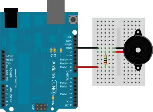
Fortunately for you, Arduino already has a pieze-electric buzzer library, and wiring it up is dead simple. The relevant GPIO pin is connected to the buzzer's positive terminal, and the buzzers negative terminal is grounded.

Wiring of Arduino Uno to Pieze Electric Buzzer

Cloud
  • 111
  • 2
1

To summarize other people's answers:

Arduinos have a whole bunch of GPIO, or general purpose I/O, pins. They can be configured as digital inputs or digital outputs. Certain pins can also be configured as analog inputs or PWM outputs.

For a simple digital pin, if it is an input, it has nearly infinite impedance. (It looks like an open connection.)

If it's an output, it acts like a current source (connected to +5V) if it's HIGH, and acts like a current sink (connected to ground) if it's LOW.

Arduino I/O pins (on most boards, check your board's specs) have a hard limit of 40mA of current flowing through them, but you should generally keep the current below 20 mA.

Is a ground connection the same as a negative connection? Sort of. Some circuits include ground, one or more positive voltage sources, and one or more negative voltage sources. Audio (analog) circuits, for example, often need ground, +12, and -12 volts.

Arduinos don't deal with negative voltages, and applying a voltage that's less than ground to any pin will likely destroy it.

Think in terms of positive voltage and ground, not positive and negative. It's less ambiguous.

Don't think of Arduino pins as being power sources. Remember that they are LOGIC pins, and only put our very small amounts of current. Trying to source or sink too much current from an Arduino pin may destroy it.

If you need to source or sink more than 20mA, use a transistor as a switch to handle the higher current load.

In addition to all that, you need to watch the total current that you pass through all your logic pins, and also the total current you draw from the power supply. Check the specs on your board and make sure you stay within the limits.
Duncan C
  • 5,752
  • 3
  • 19
  • 30
0

First of all, the Arduino doesn't supply negative voltage. It flows from positive to ground, the reference point that determines voltage.

Anyway, I'm not quite sure of the exact details of the inner-workings of the ATmega chip, but I assume it goes something like this:

  • A CPU cycle modifies a CPU register (or similar memory/latch somewhere)
  • To the output of that "register," a circuit is connected that:
    • Shorts the pin to 5V if HIGH
    • Shorts the pin to GND if LOW

I suppose the latch could be directly connected to the pin, but I think that the current draw might be too high for the latch circuit, so an external transistor is used.

That above isn't anything that's really technically correct (as these details aren't always released), but its intended purpose is to show you how it basically works from a logic point of view.

You can then manipulate the pin's connection using either of these two pieces of code:

//HIGH (== 5V)
pinMode(5, OUTPUT);
digitalWrite(5, HIGH);
//LOW (== GND; 0V)
pinMode(4, OUTPUT);
digitalWrite(4, LOW);
Anonymous Penguin
  • 6,365
  • 10
  • 34
  • 62